Rockwell Automation GV3000/SE V.6 Regulator Board 0-56921-6xx, 413338-6BU, 0-56940-6xx, 814.61.00 User Manual
Page 31
Installing Regulator Board P/N 0-56921-6xx in 1 to 20 HP @ 230 VAC Drives
4-5
Step 5.
Install the New Regulator Board in the Keypad Bracket
Refer to figure 4.3 for component locations.
Step 5.1. Remove the new Regulator board from its anti-static wrapper. Make sure
the jumper settings on the new board match those on the old board.
Step 5.2. Slide the new Regulator board into the keypad bracket. Position the board
so that seven-segment displays appear in the display window in the
keypad.
Step 5.3. Connect the green-striped keypad ribbon cable to the new Regulator board.
Align the ribbon cable connector with the Regulator board connector and
carefully push the keyboard cable in until it snaps into place. Verify that it is
locked into position by gently tugging on the cable.
Step 5.4. Connect the new Regulator board to the keypad bracket using the fasteners
removed earlier. Use the metal screws and lock washers for the two
corners of the board that have metal-plated grounding pads. Use the rivets
to mount the other two corners of the board.
To use the rivets, insert the plastic rivet bodies into the mounting holes.
Press the posts into the rivet bodies.
Important: Improper grounding of the Regulator board can result in erratic operation
of the drive.
Step 5.5. Drives with option boards only: Align the key on the Regulator board’s
34-conductor ribbon cable connector with the slot in the option board
connector. Press the ribbon cable connector in until it locks into position.
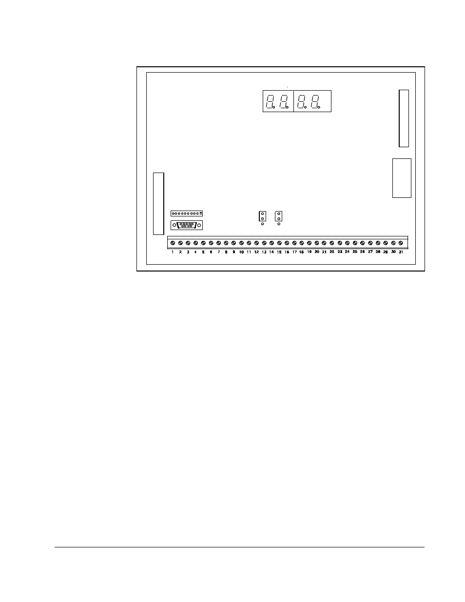
Figure 4.4 – Location of Jumpers J4 and J17 on the Regulator Board
34
-P
in
R
ibb
on
C
a
bl
e
J8
J4
J17
USER I/O TERMINAL STRIP
2
6-P
in R
ib
bon
C
abl
e
J5
J9
USER DISPLAY
J3
J7