Rockwell Automation GV3000/SE V.6 Regulator Board 0-56921-6xx, 413338-6BU, 0-56940-6xx, 814.61.00 User Manual
Page 23
Installing Regulator Board P/N 0-56921-6xx in 7.5 to 10 HP @ 460 VAC Drives
3-3
Important: The bracket is connected to the drive by wiring. Do not attempt to lift the
bracket out completely as this can damage or pull out wiring.
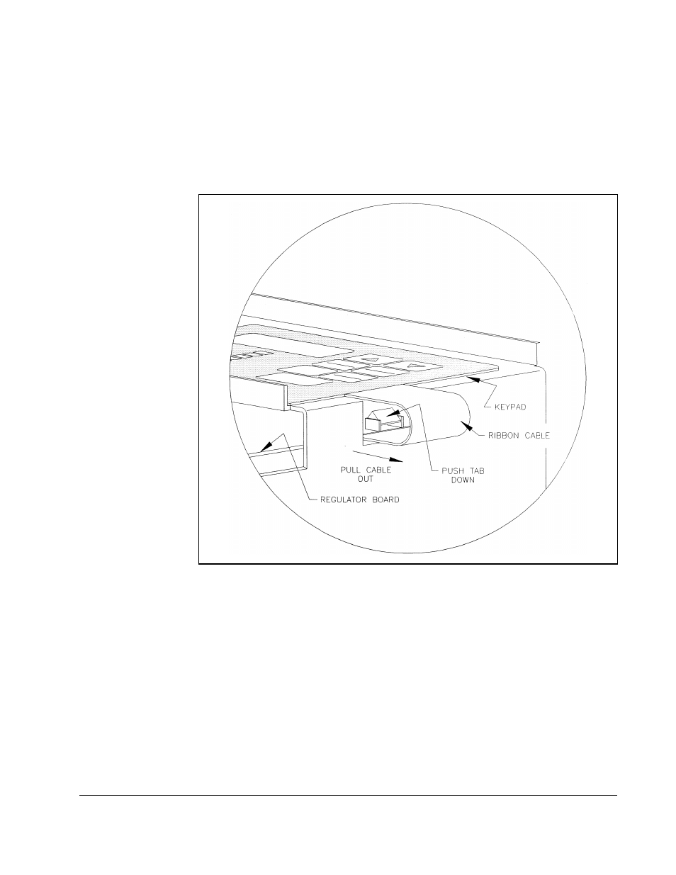
Step 3.5. Disconnect the green-striped ribbon cable from the Regulator board. This
cable is located on the right side of the drive. To disconnect this cable,
insert a small screwdriver inside the cable loop and press in on the
retaining clip in the center of the connector while pulling out the connector.
Refer to figure 3.2.
Step 3.6. Spread the retaining clips on the 26-conductor Regulator board ribbon
cable to disconnect it from the Current Feedback board. The Current
Feedback board is located on the right below the keypad.
Step 3.7. Move the keypad support bracket aside. Support the bracket to prevent
damage to the fan cable.
Step 4.
Remove the Regulator Board from the Keypad Bracket
Step 4.1. Drives with option boards only: Remove the option board from the keypad
bracket. The option board is held in place by four fasteners.
The option board fasteners might include plastic rivets. To remove a plastic
rivet, pull the post from the rivet body. Remove the body of the rivet. Use a
small pair of wire cutters or a similar tool to pry these pieces loose. Do not
cut the rivets.
Figure 3.2 – Disconnecting the Keypad Ribbon Cable from the Regulator Board