Rockwell Automation GV3000/SE V.6 Regulator Board 0-56921-6xx, 413338-6BU, 0-56940-6xx, 814.61.00 User Manual
Page 28
4-2
GV3000/SE Drive Version 6 Regulator Board Installation Instructions
Unless otherwise indicated, keep all hardware that is removed. You will need it for
reassembly. This includes option boards, screws, lock washers, and rivets.
Refer to figure 4.3 as you perform the procedure.
Important: Read and understand the warning labels on the outside of the drive
before proceeding.
Step 1.
Shut Down the Drive
Step 1.1. Disconnect, lock out, and tag all incoming power to the drive.
Step 1.2. Wait five minutes for the DC bus capacitors to discharge.
Step 1.3. Remove the cover by loosening the four cover screws.
Important: Read and understand the warning labels on the inside of the drive before
proceeding.
Step 2.
Verify That the DC Bus Capacitors are Discharged
Step 2.1. Use a voltmeter to verify that there is no voltage at the drive’s AC input
power terminals (R/L1, S/L2, T/L3).
Step 2.2. Ensure that the DC bus capacitors are discharged. To check
DC bus potential:
a. Stand on a non-conductive surface and wear insulated gloves.
b. Use a voltmeter to measure the DC bus potential at the DC bus power
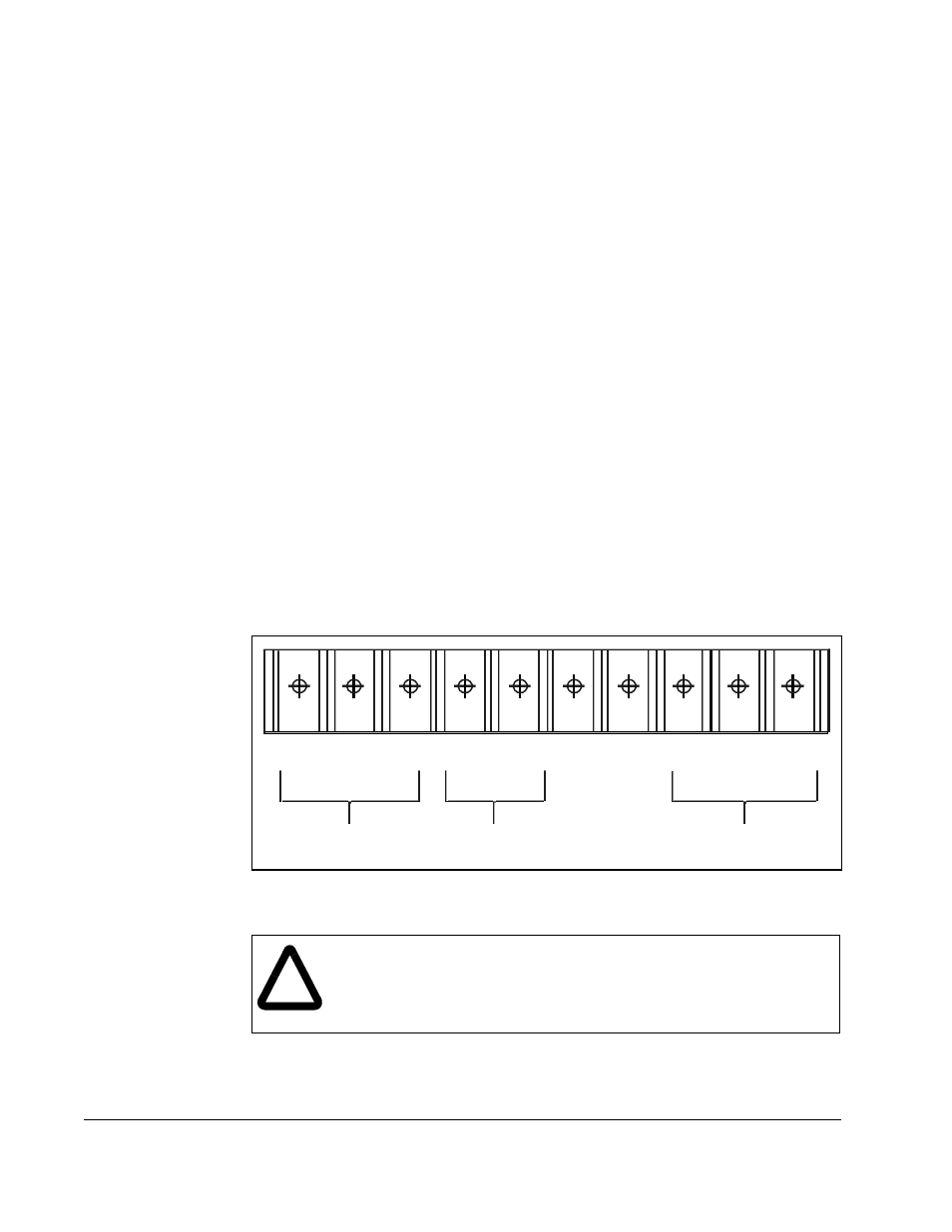
terminals shown in figure 4.1.
Figure 4.1 – DC Bus Voltage Terminals (1 to 20 HP @ 230 VAC Drives)
!
ATTENTION: The drive contains printed circuit boards that are
static-sensitive. An anti-static wristband should be worn by any person
who touches the drive components, connectors, or wiring. Erratic
machine operation and damage to, or destruction of, equipment can
result if this precaution is not followed.
W/T3
V/T2
U /T1
+
S/L2
1 0V
1 0 COM
Motor Leads
AC Power
Input Leads
DC Bus
Volts
R/L1
T/L3
–
+
–