Rockwell Automation GV3000/SE V.6 Regulator Board 0-56921-6xx, 413338-6BU, 0-56940-6xx, 814.61.00 User Manual
Page 36
5-4
GV3000/SE Drive Version 6 Regulator Board Installation Instructions
Step 3.9. Turn the Regulator board assembly over and remove the insulator from the
keypad bracket by removing a fixing screw (with lock washer) and a rivet
from the keypad bracket.
Step 4.
Remove the Regulator Board from the Keypad Bracket
Step 4.1. Drives with option boards only: Remove the option board from the keypad
bracket. The option board is held in place by four fasteners.
The option board fasteners might include plastic rivets. To remove a plastic
rivet, pull the post from the rivet body. Remove the body of the rivet. Use a
small pair of wire cutters or a similar tool to pry these pieces loose. Do not
cut the rivets.
Step 4.2. Remove the old Regulator board from the keypad bracket. The board is
fastened with two metal screws with lock washers and two plastic rivets.
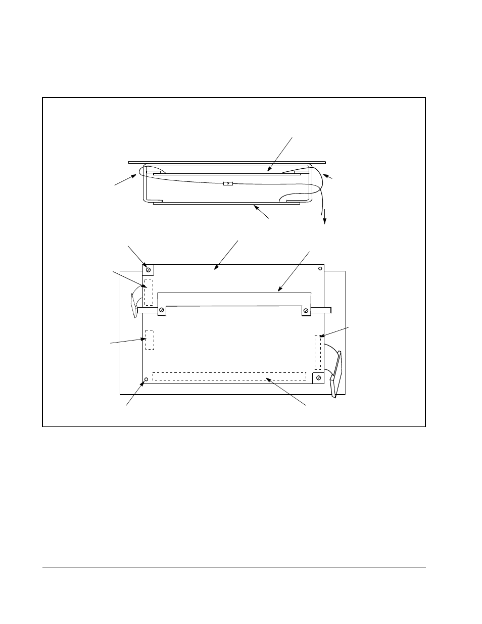
Figure 5.3 – Regulator Board’s Connection to Option Board, Keypad, and Base Board
Regulator Board
Top View
Ribbon Cable
Connecting
Regulator Board and
Base Board
Option Board
To Base Board
Front
Ribbon Cable
Connecting
Regulator Board and
Option Board
Metal Screw
Ribbon Cable
Connector to
Connect Base
Board
Ribbon Cable
Connector to
Connect Keypad
Plastic Rivet
Terminal Strip
Ribbon Cable
Connector to
Connect Option
Board
Back Side of
Insulator
Rear View of Regulator Board
Regulator Board