Rockwell Automation GV3000/SE V.6 Regulator Board 0-56921-6xx, 413338-6BU, 0-56940-6xx, 814.61.00 User Manual
Page 24
3-4
GV3000/SE Drive Version 6 Regulator Board Installation Instructions
Step 4.2. Drives with option boards only: Remove the Regulator board ribbon
connector from the option board. The connector is held in place by retaining
clips. Spread these clips to release the connector.
Step 4.3. Remove the old Regulator board from the keypad bracket. The board is
fastened with two metal screws with lock washers and two plastic rivets.
To remove a plastic rivet, pull the post from the rivet body. Remove the body
of the rivet. Use a small pair of wire cutters or a similar tool to pry these
pieces loose. Do not cut the rivets.
Step 4.4. Slide the old Regulator board out of the keypad bracket.
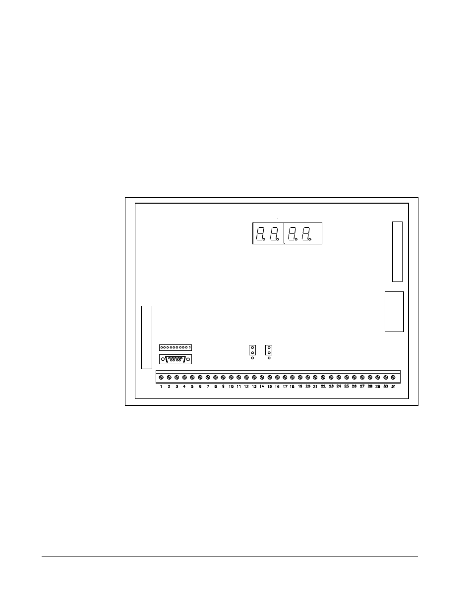
Step 4.5. Note the settings of jumpers J4 and J17 on the old Regulator board. These
jumpers are located above the center of the terminal strip as shown in
figure 3.3.
Step 5.
Install the New Regulator Board in the Keypad Bracket
Refer to figure 3.4 for component locations.
Step 5.1. Remove the new Regulator board from its anti-static wrapper. Make sure
the jumper settings on the new board match those on the old board.
Step 5.2. Slide the new Regulator board into the keypad bracket. Position the board
so that seven-segment displays appear in the display window in the
keypad.
Step 5.3. Connect the green-striped keypad ribbon cable to the new Regulator board.
Align the ribbon cable connector with the Regulator board connector and
carefully push the keyboard cable in until it snaps into place. Verify that it is
locked into position by gently tugging on the cable.
Figure 3.3 – Location of Jumpers J4 and J17 on the Regulator Board
34
-Pi
n R
ibb
on
C
a
ble
J8
J4
J17
USER I/O TERMINAL STRIP
26
-Pin
R
ibb
on C
a
ble
J5
J9
USER DISPLAY
J3
J7