Rockwell Automation GV3000/SE V.6 Regulator Board 0-56921-6xx, 413338-6BU, 0-56940-6xx, 814.61.00 User Manual
Page 43
6-4
GV3000/SE Drive Version 6 Regulator Board Installation Instructions
Step 3.
Remove the Keypad Bracket from the Drive
Step 3.1. Record the wiring to the Regulator board terminal strip.
Step 3.2. Disconnect the wiring from the Regulator board terminal strip.
Step 3.3. Drives with option boards only: Record the wiring connections to the option
board terminals. Disconnect this wiring from the option board terminal strip.
Step 3.4. Loosen the thumb screw on the left side of the keypad bracket. Hold the
bracket on the left and lift it up and to the left to separate it from the keypad
support bracket.
Important: The bracket is connected to the drive by wiring. Do not attempt to lift the
bracket out completely as this can damage or pull out wiring.
Step 3.5. Disconnect the green-striped ribbon cable from the Regulator board. This
cable is located on the right side of the drive. To disconnect this cable,
insert a small screwdriver inside the cable loop and press in on the
retaining clip in the center of the connector while pulling out the connector.
Refer to figure 6.5.
Step 3.6. Disconnect the 26-conductor Regulator board ribbon cable from the Power
Supply board (located on the right side below the keypad). You can see the
connector through the slot on the keypad support bracket. Use a small
screwdriver inserted through the slot to spread the retaining clips on the
connector to release it.
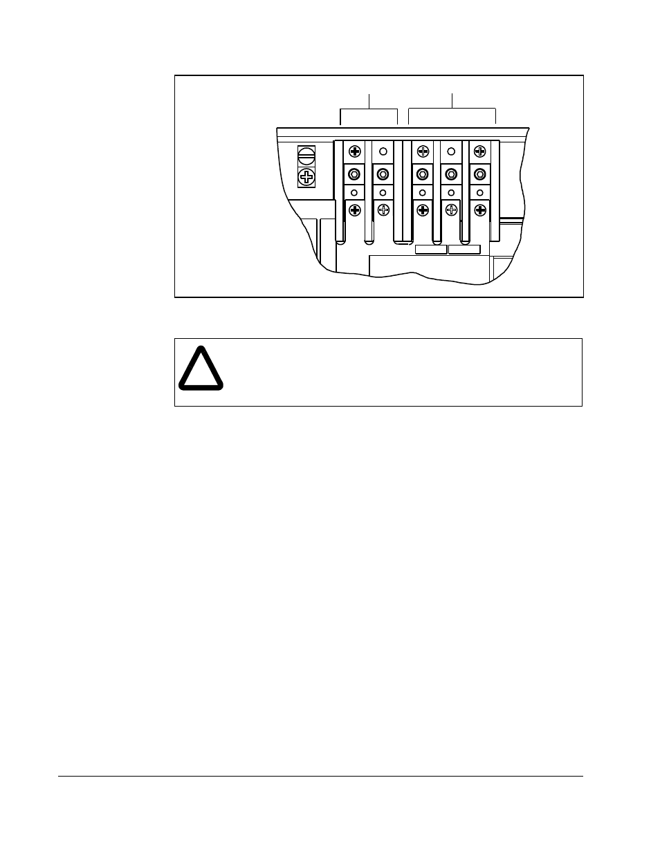
Figure 6.4 – DC Bus Voltage Terminals (25 to 60 HP @ 460 VAC Drives)
!
ATTENTION: The drive contains printed circuit boards that are
static-sensitive. An anti-static wristband should be worn by any person
who touches the drive components, connectors, or wiring. Erratic
machine operation and damage to, or destruction of, equipment can
result if this precaution is not followed.
Input Wiring
DC Bus Volts
D1
RV2
R/L1
RV3
S/L2
T/L3
-
+