Dc current test – Rockwell Automation 7000 PowerFlex Medium Voltage AC Drive (B Frame) Commissioning - ForGe Control User Manual
Page 92
92
Rockwell Automation Publication 7000-IN012B-EN-P - June 2014
Chapter 4 Commissioning the Drive
DC Current Test
Verify the isolation transformer phasing and DC Link connections. Put the drive
in DC Current Test and monitor variable "Alpha Line" and Idc feedback while
increasing the DC current through the drive rectifier.
1.
Click the Display tab, and click Feature Select from the Group Name
column.
The Feature Select parameters will appear in the right window.
2.
Click Operating Mode and click Value. Select DC Current from the
pulldown menu and click OK.
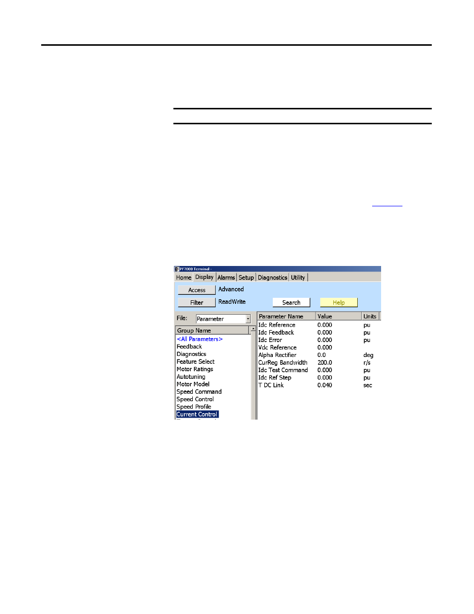
3.
Click Current Control from the Group Name column (
).
The Current Control parameters will appear in the right window.
4.
Select Idc Test Command and click Value. Type 0.1 pu in the New Value
field and click OK.
Figure 74 - Current Control Group
5.
Press the drive START button.
The drive will be pumping 0.1 pu (10%) of rated current through the DC
link. Alpha Rectifier should be approximately 90...92°.
IMPORTANT
Access level must be Advanced to perform this test.
TIP
We can also check the Idc Reference and Idc Feedback on this same screen. Idc
Reference must be at 0.1 pu and Idc Feedback must be around that same
number. Verify the Idc error stays around 0. The Idc waveform can be observed
from T21 (Idc1) on the ACB board.
The waveform must have an offset of 0.5V for each 0.1 pu of Idc Test
Command. The waveform must also never have any of the low points between
ripples go to 0V; this indicates a problem with the DC Link cabling. See the
troubleshooting section for sample waveforms.