Rockwell Automation 7000 PowerFlex Medium Voltage AC Drive (B Frame) Commissioning - ForGe Control User Manual
Page 72
72
Rockwell Automation Publication 7000-IN012B-EN-P - June 2014
Chapter 4 Commissioning the Drive
Each drive has a power cable that supplies 15V DC from an AC/DC power
supply to the firing cards (SPGDB). This cable has one input you can connect to
an AC source (120/240V, 50/60 Hz) and 18 sets of outputs you can connect to
the SCR self-powered gate driver boards.
Plug the AC power connector on the test cable into an appropriate AC source.
The other eighteen 3-pin connectors plug into the SCR SPGDB board terminals
labeled TB3 – Test Power (see
). The number of eighteen 3-pin
connectors used depends on the voltage and configuration of the drive rectifier
section.
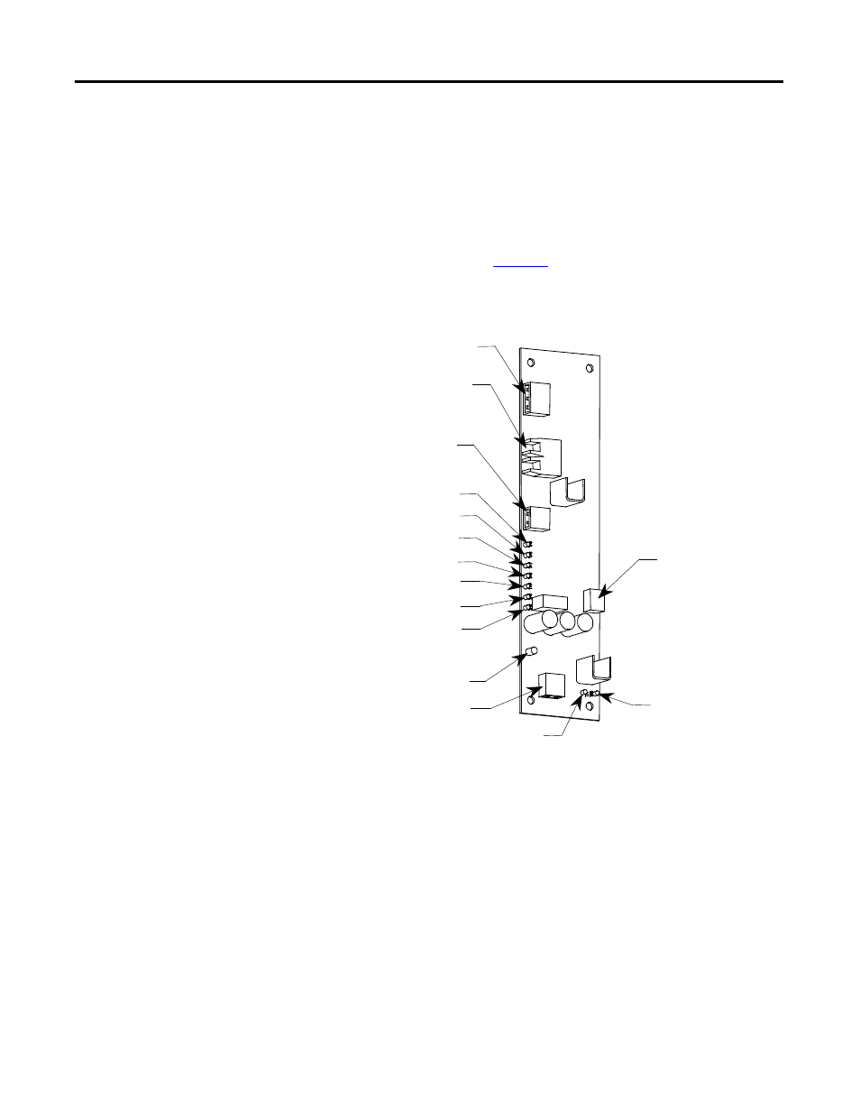
Figure 57 - Self-Powered Gate Driver Board Test Power Terminal
Put the drive in Gating Test Mode and the rectifier automatically enters Test
Pattern gating mode. LED 1 – Gate Pulse (Yellow) should light up and pulsate at
the same device firing frequency. The other LEDs light up as the firmware sends a
gating signal to every SCR.
There is also a Gating Test that fires the individual devices one at a time, in what is
described as a Z-pattern. For each section, the Top Left device turns on for 2
seconds, then turns off. The next device to the right turns on for 2 seconds, and
the pattern continues.
TB3 - Test power connection
OP1, OT1 - Fiber optic transmitter
and receiver
TB2 - Temperature sensor
power connection
TP9
TP8
TP7
TP6
TP3
TP4
TP5
TB4 - Gate and cathode
thyristor connection
LED
TB1 - Snubber connection
TP1
TP2