Harmonic analysis (required for pwm drives only) – Rockwell Automation 7000 PowerFlex Medium Voltage AC Drive (B Frame) Commissioning - ForGe Control User Manual
Page 114
114
Rockwell Automation Publication 7000-IN012B-EN-P - June 2014
Chapter 4 Commissioning the Drive
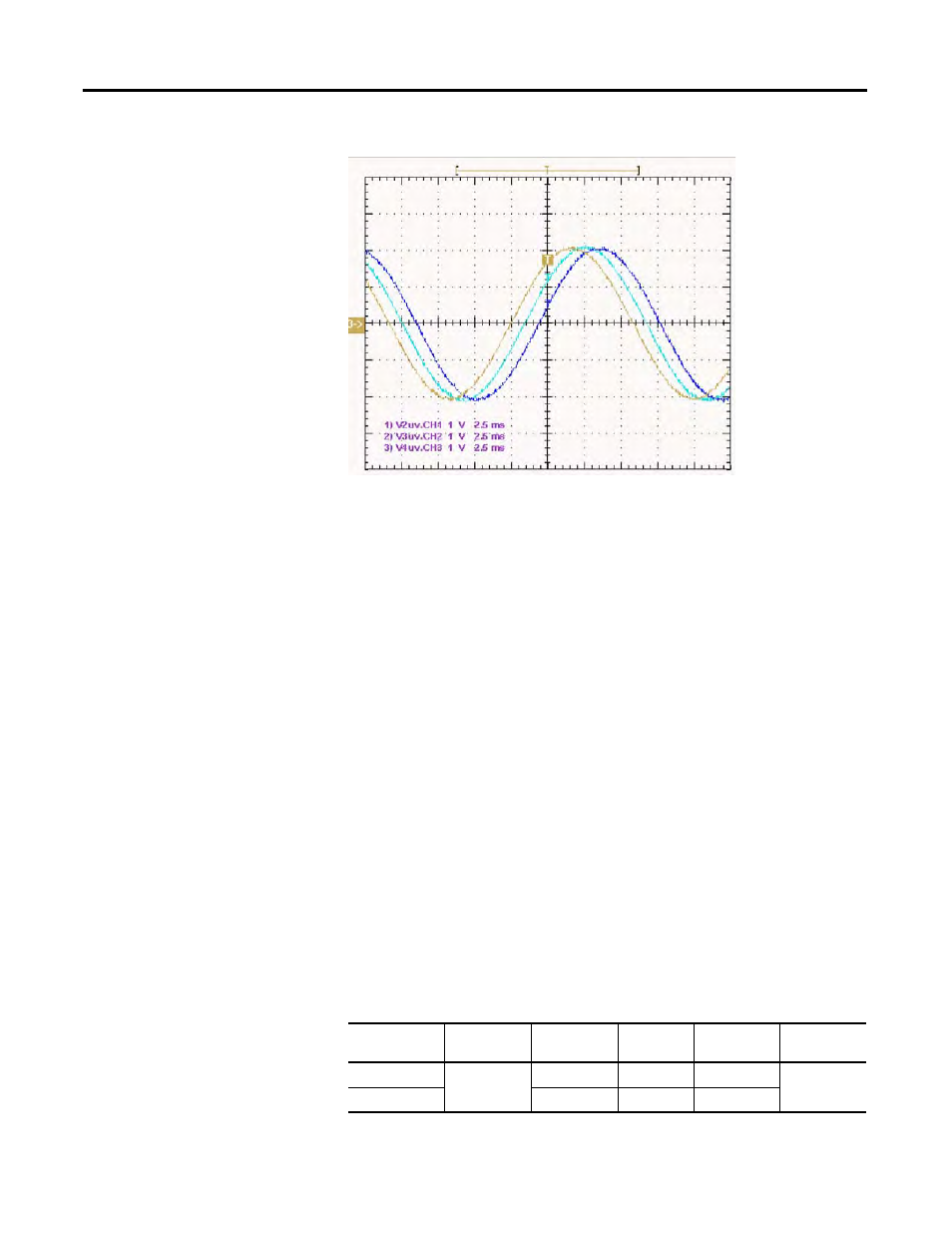
Figure 81 - Sample waveforms: 20 deg phase shift between master and 2 slave bridges
Verify the phase shift is:
• V2uv must be 0º
• V3uv must be -20º
• V4uv must be +20º
Harmonic Analysis (required
for PWM drives only)
Measure the harmonic (resonance) levels at the input to the drive. If you notice
considerable distortion in the waveforms, you MUST send those waveforms to
MV Support via e-mail at [email protected], and then call
519-740-4790 (option 1) to discuss the issue and action plan. After-hours, call
(519-503-0346) to talk with MV Tech Support Specialist. Outside North
America, call 1-440-646-3434 and request MV Tech Support.
Summary:
• Close all drive input contactors. If the drive input contactor configuration
is set to NOT RUNNING, temporarily change it to ALL FAULTS.
• Verify the drive is not running when capturing these waveforms.
• Capture line voltage at ACB test point “V2uv” and line current at ACB
test point “I2u”.
• Label the waveforms as “V2uv”, and “I2u”.
• Save the worksheet as “Harmonics (Drive Not Running)”.
Table 5 - Oscilloscope Settings
Oscilloscope
Time Base
Wave Form
Test-Point
Waveform
Label
Sheet Name
Chan. 1
10 ms/div.
Line Voltage
V2uv
V2uv
Harmonics (drive
not running)
Chan. 2
Line Current
I2u
V2vw