Start/stop control circuit – Rockwell Automation 7000 PowerFlex Medium Voltage AC Drive (B Frame) Commissioning - ForGe Control User Manual
Page 75
Rockwell Automation Publication 7000-IN012B-EN-P - June 2014
75
Commissioning the Drive Chapter 4
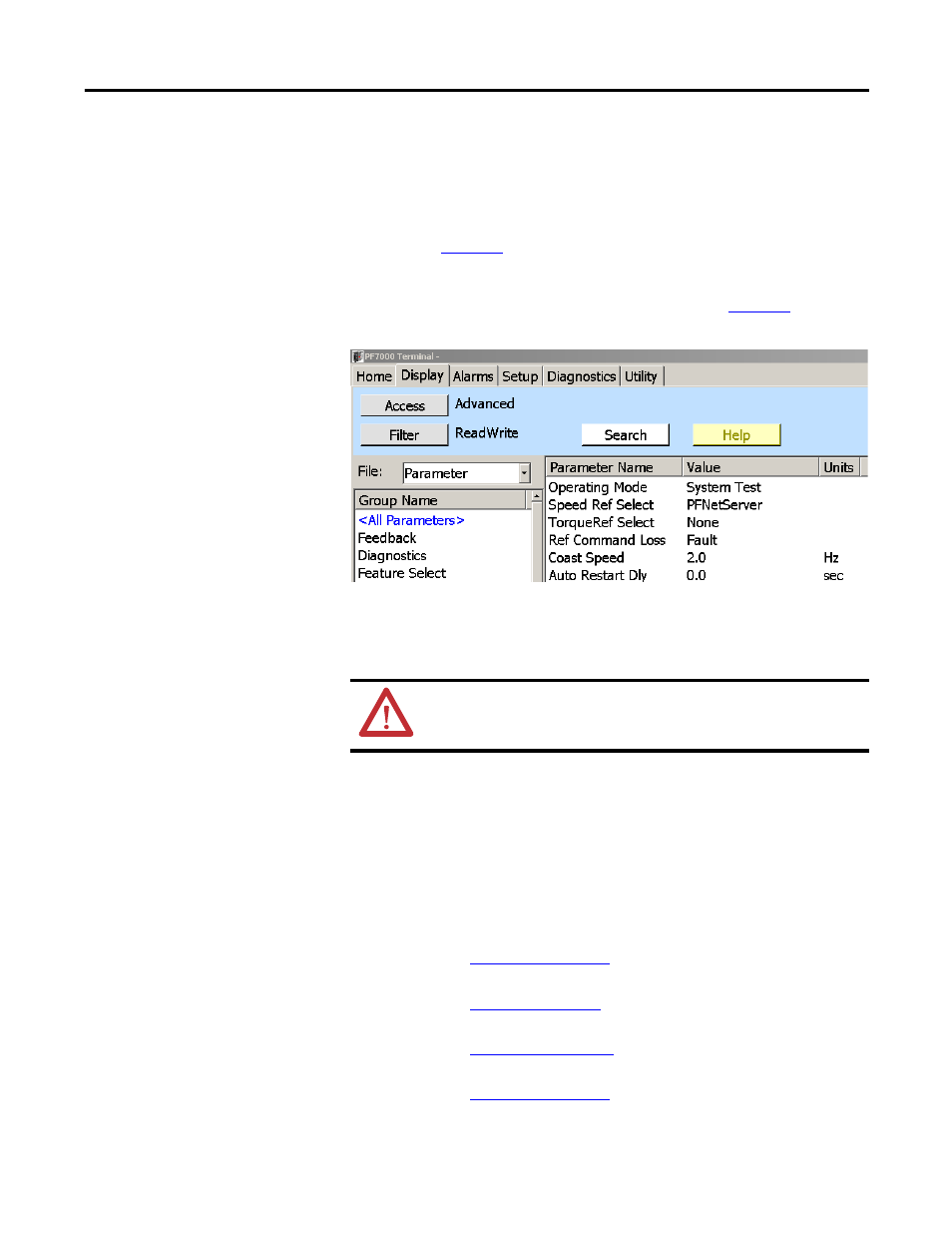
1.
Click the Display tab and select Feature Select from the Group Name
column.
The group parameters show in the right window.
2.
Select Operating Mode and click Value to open the Operating Mode
dialog (
Figure 55
).
3.
Select System Test from the New Value pulldown menu and click OK.
The Operating Mode Value changes to System Test (
Figure 59 - System Test Mode
Start/Stop Control Circuit
Once the drive is in System Test mode, ensure that the stop/start circuit functions
as desired. If necessary, review the electrical schematic drawings prior to
performing this test to better understand the control circuit.
Start the drive in local control while observing the system vacuum contactors or
customer supplied circuit breakers. If you must troubleshoot Rockwell
Automation medium voltage switchgear, refer to the following publications:
• Publication
Medium Voltage Controller, Bulletin
1512B, Two-High Cabinet, 400 Amp • User Manual
• Publication
OEM Starter Frame and Components •
Installation Manual
• Publication
edium Voltage Contactor, Bulletin
1502, 400 Amp (Series D) • User Manual
• Publication
edium Voltage Contactor, Bulletin
1502, 400 Amp (Series E) • User Manual
TIP
You can check the entire system without medium voltage. As long as all the
contactors have test power, you can start, stop, E-Stop, trigger faults, check
remote IO, check PLC inputs, and verify other functions.
Ensure that the drive is no longer running in system test mode
prior to applying medium voltage to the drive line-up. Failure
to do so may result in equipment damage.
ATTENTION: Ensure that the drive is no longer running in system test mode
prior to applying medium voltage to the drive line-up. Failure to do so may
result in equipment damage.