Control power tests, Three-phase input – Rockwell Automation 7000 PowerFlex Medium Voltage AC Drive (B Frame) Commissioning - ForGe Control User Manual
Page 59
Rockwell Automation Publication 7000-IN012B-EN-P - June 2014
59
Commissioning the Drive Chapter 4
Control Power Tests
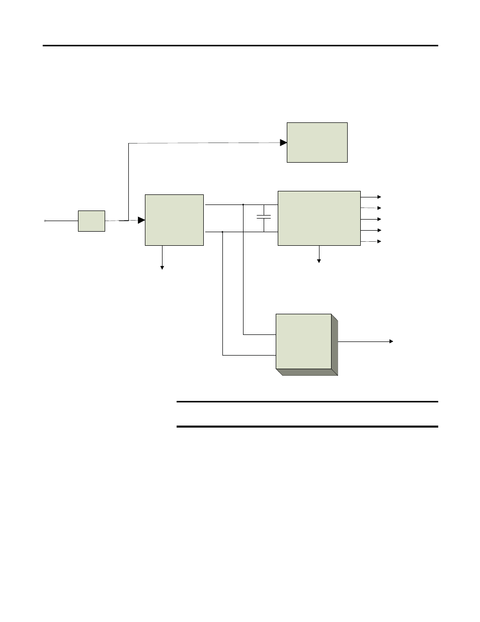
Although there are a variety of options available to customers that will affect the
control power distribution within the drive, the input will always be as illustrated
below:
Figure 44 - Control power distribution
Three-Phase Input
In the 3-phase input configuration, the customer supplies 3-phase control power
into the disconnect switch (Labeled DS1 on the Electrical Schematics). From
that point, the power is distributed to the 3-phase fan and to the power supplies
through a single phase CPT. The output of the single phase CPT powers all the
power supplies and controls within the drive. The 3-phase control should be
measured at the input to DS1. If the rating matches the designation on the
electrical schematic, it is acceptable to apply control power to the drive. Take
necessary measures to rectify the control power level in the event that it does not
meet the design specifications.
-Printer
-Operator Interface
-Relays
DC/DC CONVERTER
AC/DC Converter
56V DC
1000W/
1500W
+5V-LOGIC
+/-15V-LOGIC
+/-24V-HECS
+24V-ISOLATORS
+24V-XI0
SENSE CABLE
20V
C Hold-up
20V Isolated
Gate Driver
Power Supp ly
DC Fail
Line
Filter
Customer
Supp lier
120V
1-ph
600W/
Inverter only for SPS drives
IMPORTANT
Prior to energizing the drive, verify that the control power feeding into the
input breakers is rated as designated on the electrical diagram.