3 main routine, 4 logic routine – Rockwell Automation 9329 Drive Application Software Tension Control Gen. Units User Manual
Page 16
FM – Tension Control
Drive Application Software – page 16 of 52
4.3 Main routine
The Main routine consists of four rungs of ladder logic programming. A rung description
briefly describes the Input and Return (output) parameters of the JSR instructions for each
routine called. Temporary tags have been entered for each input parameter and each return
parameter. The tag names entered in the JSR’s are not declared. The user must replace
these tag names with existing project tags or create new tags. The routine will show an error
until all input and return parameters are satisfied. The input parameters may also be entered
as actual values. If an input parameter is set to a value and not a tag, the value cannot be
edited in run mode. Values entered directly in the JSR should be constants that do not
change during machine operation. Specific formatting is required for values entered directly
in the JSR.
NOTE: For Application Module users, the tags in the JSR’s are predefined and configured for
operation. No additional integration is necessary.
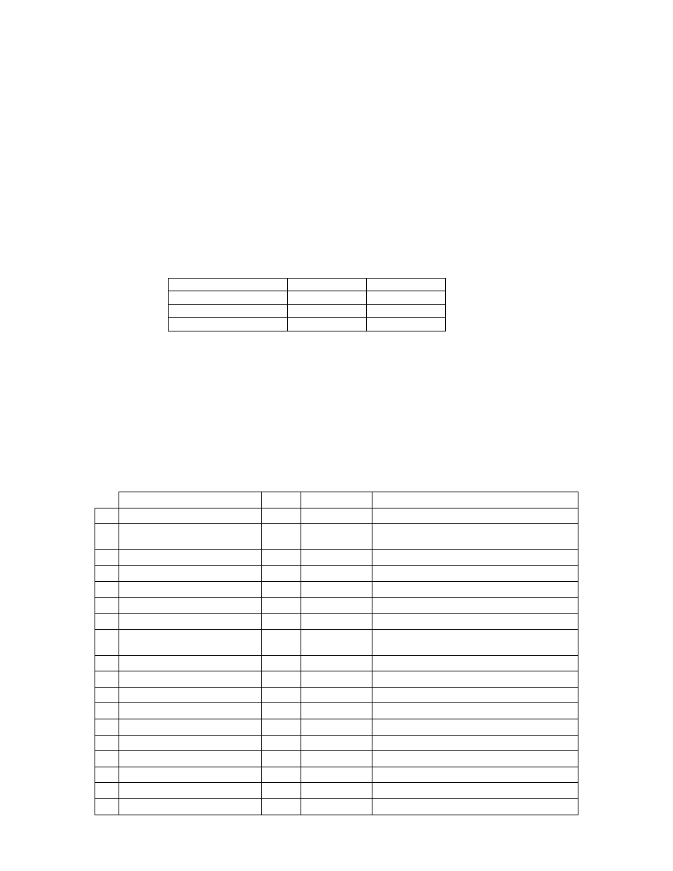
Data Type
Format
Example
B = Boolean
x
0 or 1
I = Integer
x
123
R = Real (Float)
x.x
3.4 / 13.0
If any signal scaling is required to interface the FM into the user application, the user may use
the main routine for this programming. Note; Scaling for inputs to the routines should be
done before the JSR and any scaling applied to the return values from the routines should
be done after the JSR.
4.4 Logic Routine
The Logic Routine is used to configure the Tension Control Function Module. In this routine
the selected tension mode is tested, constants for speed and torque scaling are generated,
and sections of code are enabled or disable depending on the tension mode selected.
Input Parameters
Name
Type
Range
Description
1 CtrlEnbl
BOOL
0 to 1
Enables the Tension Control Module
2 Running
BOOL
0 to 1
Releases the tension regulator when the
machine is running
3 TenCtrl
BOOL
0 to 1
Select Tension Control
4 TrqCtrl
BOOL
0 to 1
Select Torque Control
5 DanCtrl
BOOL
0 to 1
Select Dancer Control
6 TrqTrim
BOOL
0 to 1
Regulator adjust Trq Reference
7 SpdTrim
BOOL
0 to 1
Regulator adjust Speed Reference
8 TenZoneDwStream
BOOL
0 to 1
Location of the Tension Zone with
respect to the controlling section
9 ReverseRotation
BOOL
0 to 1
selects the sign of the Torque signal
10 TrimHoldHigh
BOOL
0 to 1
Trim Regulator Hold High
11 TrimHoldLow
BOOL
0 to 1
Trim Regulator Hold Low
12 TenRfStall
BOOL
0 to 1
Stall Tension Reference Selected
13 TrqFbJLoss
BOOL
0 to 1
Torque Fdbk includes Inertia & Friction
14 TrqMemEnbl
BOOL
0 to 1
Torque Memory Enable
15 TrqFolwCtrl
BOOL
0 to 1
Torque Follower Control
16 TenMax_EU
REAL
NA
Tension Maximum [Engineering Units]
17 RadiusCalc_EU
REAL
NA
Calculated Radius
18 GearRatio
REAL
NA
Gear Ratio [Motor Speed/Roll Speed]