Fiber optic cabling, Air pressure sensor – Rockwell Automation 7000A PowerFlex Medium Voltage AC Drive (A Frame) - ForGe Control (PanelView 550) User Manual
Page 145
Component Definition and Maintenance 4-19
7000 “A” Frame
7000A-UM151D-EN-P – March 2013
Fiber Optic Cabling
The equipment is provided with fiber optic cabling as a means of
interfacing the low voltage control to the medium voltage circuits. The
user of the equipment should never need to change the routing of the fiber
optic cables.
Each end of a fiber optic cable is provided with a connector that plugs and
latches into its respective location on a circuit board. To disconnect a fiber
optic cable, depress the ridged plastic tab at the end connector and pull.
To install a fiber optic cable insert the fiber optic port of the circuit board
so that the plastic tab latches into place.
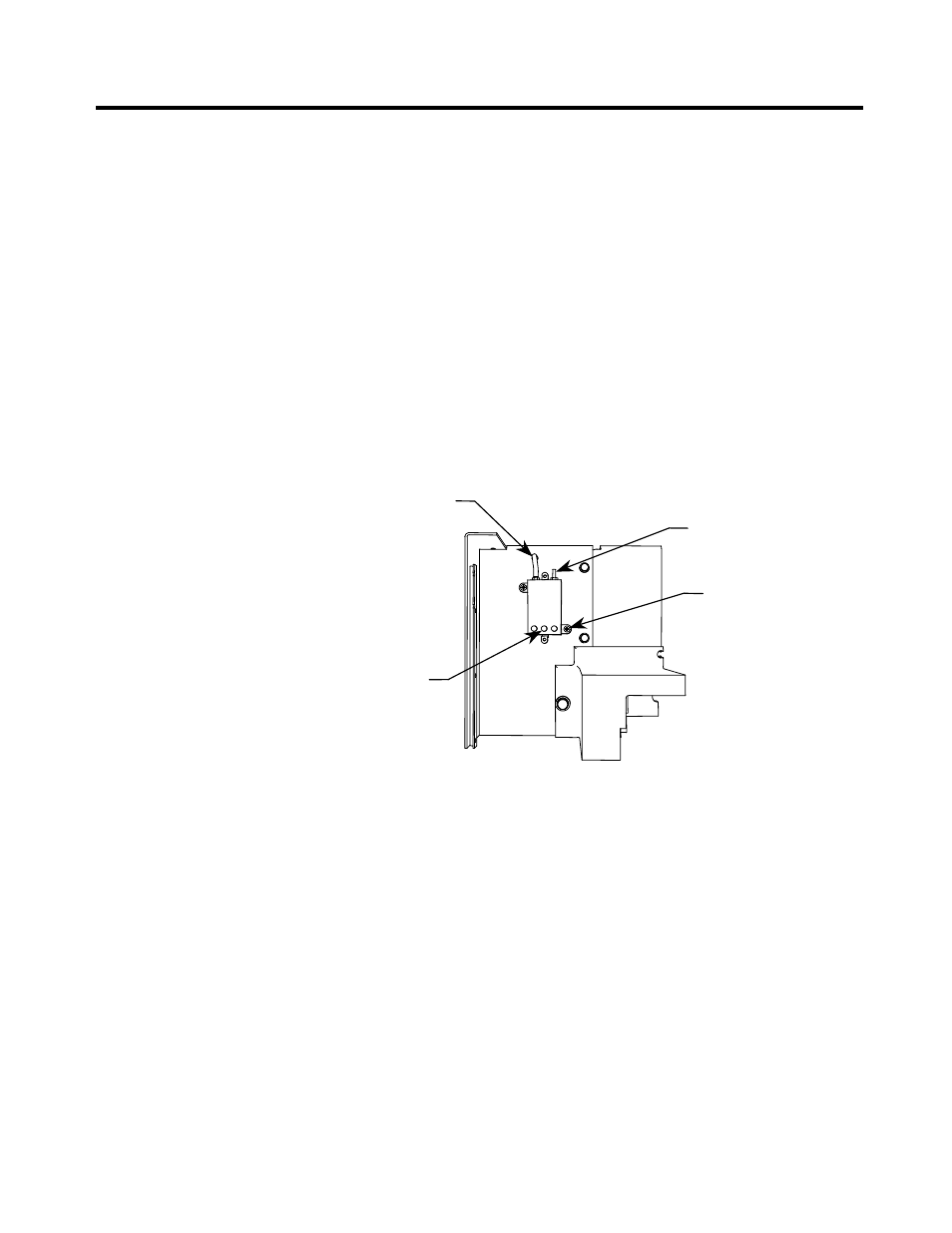
Air Pressure Sensor
An air pressure sensor is located in both the converter cabinet and the
integral rectifier transformer cabinet (if applicable). In both cases, it is
located in the upper left-hand quadrant of the cabinet.
Flexible tube for
low pressure port
High pressure port
Mounting screw
Wire terminals
Figure 4.15 – Air Pressure Sensor
The air pressure sensor measures the difference in air pressure between
the front and rear of the converter modules/integral rectifier transformer.
A small direct current voltage signal is transmitted to the control circuits.
In the event of reduced fan performance or air blockage for either the
converter or the transformer, the measured differential pressure will be
reduced and a warning message will appear on the console. A likely
cause of the warning message would be laden filters at the inlet.
If, as a result of blockage or fan failure, flow becomes so reduced that
there is a risk of thermal damage for either the converter or transformer, a
fault signal will cause drive shutdown.