2ć14 – Rockwell Automation 1779-KP3R DATA HIGHWAY II User Manual
Page 30
Installing the 1779-KP3
Communication Interface
Chapter 2
2Ć14
You can set up a PLC–3 backup system in three ways, using an:
I/O Scanner–programmer Interface Module (1775–S4A), a PLC–3 I/O
Scanner Communication Adapter Module (1775–S5) or a Memory
Communication Module (1775–MX) without the KP3
S4A, S5, or MX with the KP3
S4A or S5 with an MX, and the KP3
The following sections discuss each of these possibilities.
Using an S4A, S5 or MX Without the KP3
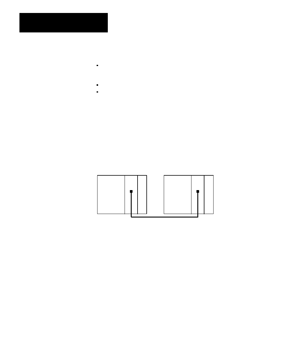
You can connect the primary and backup PLC–3s by connecting the
1775–S4A (1775–S5, or 1775–MX) in each PLC–3 processor (figure 2.7).
Figure 2.7
Backup Cabling Without the KP3
S4A KP3
Primary PLC-3
Backup PLC-3
Backup
11007-I
S4A KP3
Backup
This method is recommended when the application process requires that
the Data Highway II switchover of communication happens after the
backup PLC–3 has taken control of the live I/O. Use this method when
the KP3 is involved in primarily supervisory transactions. This method is
fully explained in the PLC–3 Backup Concepts Manual (publication
1775–6.3.1).
You can also directly connect the S5 or MX modules in the primary and
backup PLC–3s.
Using the S4A, S5, or MX With the KP3
You can connect the S4A (S5 or MX) module to the KP3 module in both
the primary and backup PLC–3s. Then connect the KP3 in the primary
PLC–3 to the KP3 in the backup PLC–3 (figure 2.8).
Installing a Back-up PLC-3
System on Data Highway II