Rockwell Automation 1779-KP3R DATA HIGHWAY II User Manual
Page 11
Overview
Chapter 1
1-5
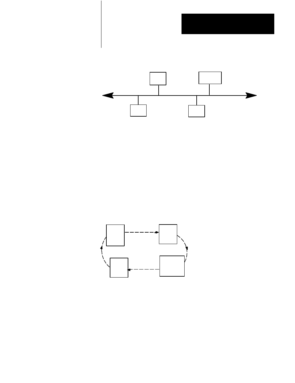
Figure 1.5
Data Highway II is a Physical Bus Network
Node
Node
Node
Node
1
16
7
31
10995-I
While the physical layout of the Data Highway II network is a bus, the
method of access to the network is a logical ring. Nodes are allowed to
communicate on the network while they posses the token. This token is
passed around the ring according to the nodes’ addresses on the Data
Highway II link. While a node possesses the token it is the master, and it
is the only node that can send commands out to the network. When it is
finished, the token passes to the node with the next highest address,
regardless of the node’s physical proximity to the previous node (figure
1.6).
Figure 1.6
A Conceptual View of Data Highway II Logical Ring Communication
Node
Node
Node
Node
1
16
7
31
10996-I
When a node leaves the ring unexpectedly, the ring performs a recovery
procedure. The node with the next lowest node number attempts to pass
the token to the exiting node, but because it cannot, the ring must undergo
a recovery procedure to rebuild itself. When the message returns to the
inquiring node, the node can then pass the token to the node that has the
next highest number.