Rockwell Automation 1779-KP3R DATA HIGHWAY II User Manual
Page 13
Overview
Chapter 1
1-7
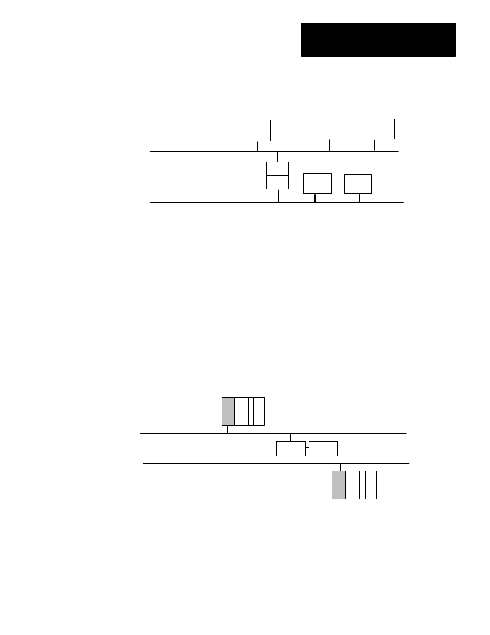
Figure 1.8
Two Data Highway II Links
Node
Node
Node
KP5
KP5
Node
Node
Data Highway II Link 1
Data Highway II Link 2
A
B
C
D
E
10998-I
Figure 1.8 shows two Data Highway II links. Notice that to ‘‘Node A”,
‘‘Node B” is on–link, and ‘‘Node D” is off–link. Data Highway II nodes
consider other nodes ‘‘off–link” if, to communicate with them, the Data
Highway II nodes have to cross a bridge.
The link numbers become an important factor when you are addressing
messages. For example, if you have two Data Highway II networks
bridged together via two Allen–Bradley KP5 modules, the two links have
different link numbers (Figure 1.9). You use this link information inside
your message instruction (see Chapter 3 on Programming for more
information).
Figure 1.9
Example of Two Data Highway II Links
Data Highway II Link 1
PLC-2
Link = 1
PLC-3
Link = 2
KP5
Data Highway II Link 2
KP5
10999-I
Nodes on the same link (on–link), have the same link number; nodes on
different link (off–link), have different link numbers. Note that your local
link may always be specified as link zero; by default, the link you are
connected to is considered zero with respect to other local nodes you may
be communicating with.