Chapter objectives, Printed circuit boards, Set the switches on the host board – Rockwell Automation 1779-KP3R DATA HIGHWAY II User Manual
Page 17
Chapter
2
2Ć1
Installing the 1779-KP3 Communication Interface
This chapter contains the information you need to install your 1779–KP3
Communication Interface module. It covers the following topics:
printed circuit boards
setting the switches on the host board
setting thumbwheel switches
installing the KP3 into the PLC–3 chassis
using the LIST option to select additional KP3 parameters
connecting the KP3 to Data Highway II
connecting a PLC–3 to multiple Data Highway II links
how a PLC–3 backup system works on Data Highway II
installing a backup PLC–3 on Data Highway II
The 1779–KP3 interface is a single module that consists of two printed
circuit boards:
the host board
the media access controller (MAC) board
There are switches associated with each of these boards. Read the
following section before installing your module.
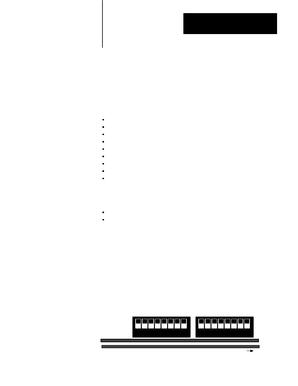
Before you install your KP3 interface, you must set the switches located
inside the module on the host board. There are two groups of switches:
Group 1 and 2. You can view them from the top of the module, looking
inside at the board (figure 2.1).
Figure 2.1
Top View of Switches on the KP3 Module's Host Board
1 2 3 4 5 6 7 8
Host Board
Mac Board
Group 1
Group 2
1 2 3 4 5 6 7 8
Front of Module
11001-I
Chapter Objectives
Printed Circuit Boards
Set the Switches on the Host
Board