Rockwell Automation 1779-KP3R DATA HIGHWAY II User Manual
Page 20
Installing the 1779-KP3
Communication Interface
Chapter 2
2Ć4
Table 2.B
Group 2 Switch Settings
If:
Set
switch
number:
To:
you want the KP3 to accept write commands to the program
areas of the PLC-3 memory, regardless of the PLC-3
keyswitch position
4
ON
you want the PLC-3 keyswitch position checked to
determine if write commands are allowed to the program
areas of PLC-3 memory
OFF
you want the KP3 to accept write commands to the data
table areas of the PLC-3 memory, regardless of the PLC-3
keyswitch position
5
ON
the PLC-3 keyswitch position checked to determine if write
commands are allowed to the data table areas of PLC-3
memory
OFF
you want the KP3 to accept write commands to the status
areas of memory, regardless of the PLC-3 keyswitch
position
6
ON
you want the PLC-3 keyswitch position checked to
determine if write commands are allowed to the status areas
of PLC-3 memory
OFF
Important: Do not touch switches 1, 2, and 3; they are reserved for future use.
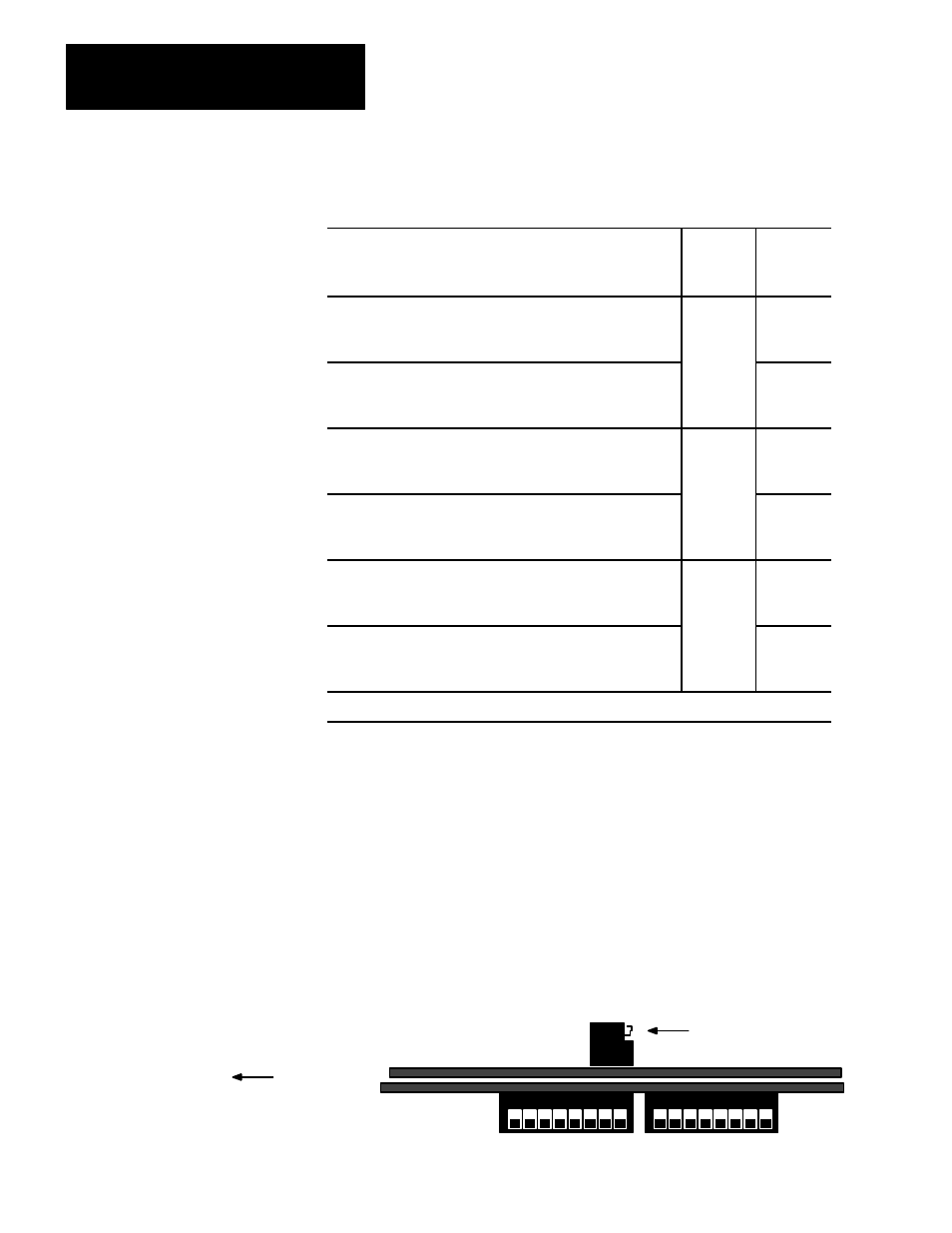
The MAC Board Switch Your Module May Have
If your 1779–KP3 Interface has a series A MAC board, you will also have
a 2–switch group on the MAC board. You can view it from the top of the
module looking down at the MAC board. Figure 2.3 shows the location
of this switch in relation to the host board switches; this is a side view of
this group. Note that this switch does not exist on redundant modules
(1779–KP3R) or 1779–KP3 modules with series B MAC boards.
Figure 2.3
The MAC Board Switch Group
1 2 3 4 5 6 7 8
Host Board
Mac Board
Side view of 2-switch Group
1 2 3 4 5 6 7 8
Front of Module
11003-I