Input channel filtering -14, Input channel filtering – Rockwell Automation 1746-XXXX SLC 500 4-Channel Analog I/O Modules User Manual User Manual
Page 52
Publication 1746-UM005B-EN-P - June 2004
4-14 Module Operation and System Considerations
Input Channel Filtering
The input channels for all of the analog modules incorporate
extensive on board signal conditioning. The purpose of this
conditioning is to reject the high frequency noise that can couple into
an analog input signal while passing the normal variations of the input
signal. The conditioning is performed by passing the input signal
through a 6 pole Gaussian digital filter.
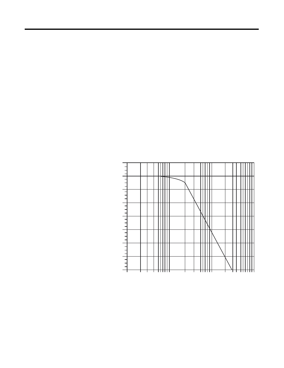
The sharp cut-off of this filter is demonstrated in the frequency
response plot shown below. Frequency components of the input
signal at or below the filter corner frequency of 10 Hz are passed with
under 3 dB of attenuation. This pass band allows the normal variation
of sensor inputs such as temperature, pressure and flow transducers to
be input data to the processor.
Noise signals coupled in at frequencies above the 10 Hz pass band is
sharply rejected. An area of particular concern is the 50/60 Hz region,
where pick up from power lines can occur. From the frequency
response diagram, you see that a 60 Hz signal on the plus (+) input
with respect to the minus (-) input is attenuated by over 55 dB (60 Hz
normal mode rejection).
1000
100
10
-140
-120
-100
-80
-60
-40
-20
0
20
1
Output
Amplitude in dB
Frequency in Hz