Procedures, Procedures -2 – Rockwell Automation 1746-XXXX SLC 500 4-Channel Analog I/O Modules User Manual User Manual
Page 16
Publication 1746-UM005B-EN-P - June 2004
2-2 Quick Start for Experienced Users
Procedures
1.
Check the contents of shipping box.
Reference
Unpack the shipping box making sure that the contents include:
•
Analog I/O module (Catalog Number 1746-Series)
•
installation instructions (publication 1746-IN008)
If the contents are incomplete, call your local Allen–Bradley representative for assistance.
2.
Determine your power requirements for the modular controller.
Reference
Review the power requirements of your system to see that your chassis supports placement of the
analog module.
•
For modular style systems, calculate the total load on the system power supply using the
procedure described in the SLC 500 Modular Hardware Style User Manual (publication
1747-UM011) or the SLC 500 Family System Overview (publication 1747-SO001).
•
For fixed SLC 500 controllers, refer to the SLC 500 Fixed Hardware Style Installation &
Operation Manual (publication 1747-6.21).
Chapter 3
(Installing and
Wiring Your
Analog Module)
Appendix A
(Specifications)
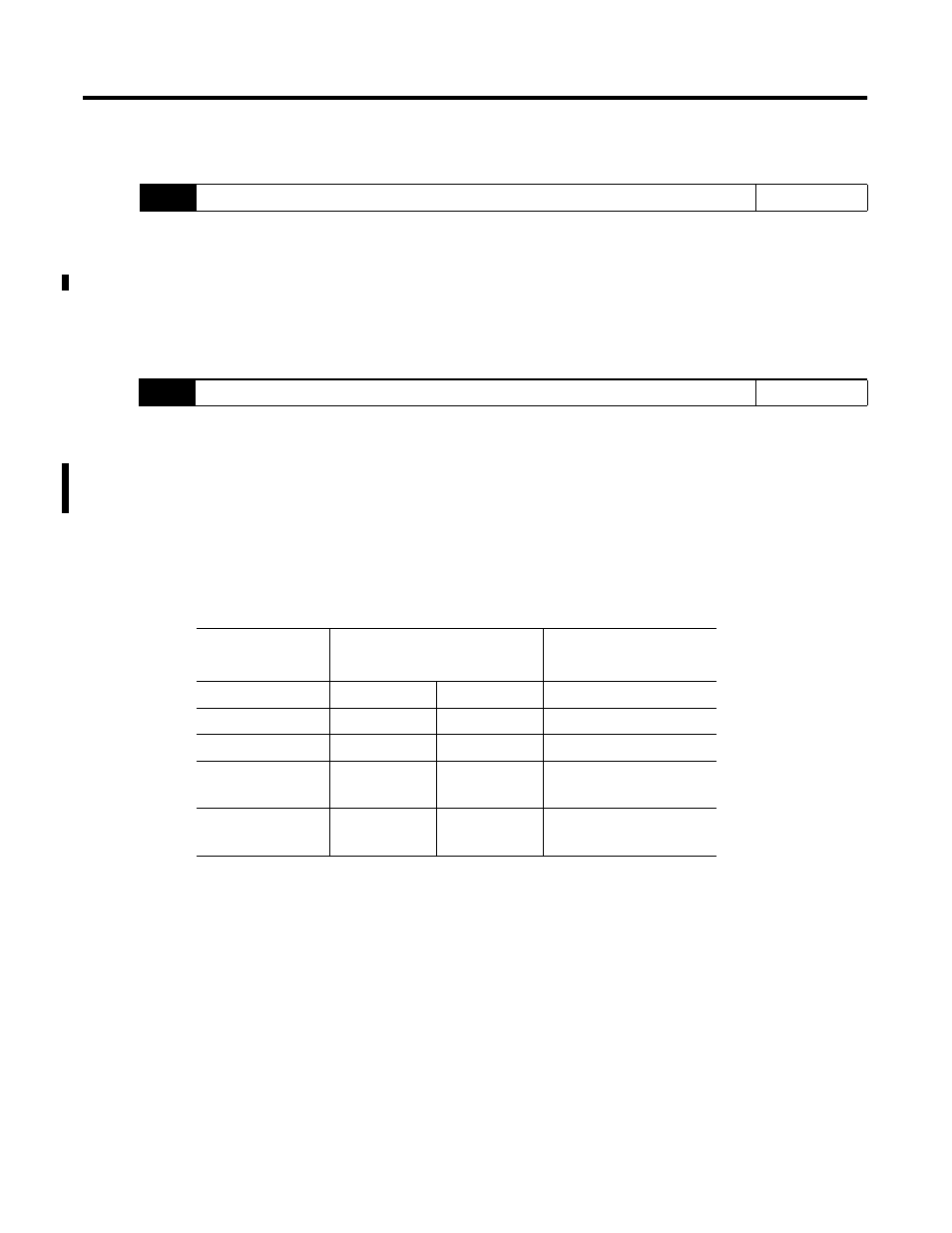
Catalog Number
Backplane Current Draw
External 24V dc Power
Supply Tolerance
5V (max.)
24V (max.)
1746-NI4
35 mA
85 mA
NA
1746-NIO4I
55 mA
145 mA
NA
1746-NIO4V
55 mA
115 mA
NA
1746-NO4I
55 mA
195 mA
24 ±10% at 195 mA max.
(21.6 to 26.4V dc)
(1)
1746-NO4V
55 mA
145 mA
24 ±10% at 145 mA max.
(21.6 to 26.4V dc)
(1)
Required for some applications if SLC 24V power is not readily available.