Minimizing electrical noise on analog modules, Wiring schematic for single-ended analog input, Minimizing electrical noise on analog modules -15 – Rockwell Automation 1746-XXXX SLC 500 4-Channel Analog I/O Modules User Manual User Manual
Page 37
Publication 1746-UM005B-EN-P - June 2004
Installing and Wiring Your Analog Module 3-15
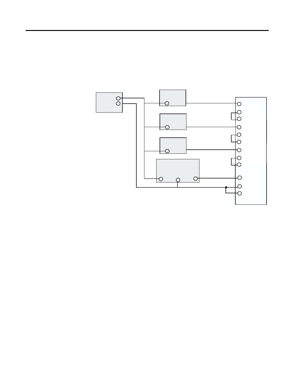
Wiring Schematic for Single-ended Analog Input Connections
Minimizing Electrical
Noise on Analog Modules
Inputs on analog modules employ digital high frequency filters that
significantly reduce the effects of electrical noise on input signals.
However, because of the variety of applications and environments
where analog modules are installed and operating, it is impossible to
ensure that all environmental noise will be removed by the input
filters.
Although it is not the purpose of this manual to address SLC 500
system procedures, several specific steps can be taken to help reduce
the effects of environmental noise on analog signals:
•
install the SLC 500 system in a properly rated (i.e., NEMA)
enclosure. Make sure that the SLC 500 system is properly
grounded.
•
use Belden cable #8761 for wiring the analog modules making
sure that the drain wire and foil shield are properly earth
grounded.
•
route the Belden cable separate from any other wiring.
Additional noise immunity can be obtained by routing the cables
in grounded conduit.
Transmitter
+
Transmitter
Supply
Signal
+
IN 1 +
IN 1 –
ANL COM
IN 3 +
IN 3 –
ANL COM
+
Power
Supply
–
IN 0 +
IN 0 –
ANL COM
IN 2 +
IN 2 –
ANL COM
Transmitter
+
Signal
Transmitter
+
Signal
Ground
NI4
Signal
When wiring single-ended analog input devices to the analog input card, the number of total wires
necessary can be limited by using the ANALOG COMMON terminal. Note that dif ferential inputs are
more immune to noise than single-ended inputs.