Configuring your module, Configuring your module -5 – Rockwell Automation 1746-XXXX SLC 500 4-Channel Analog I/O Modules User Manual User Manual
Page 27
Publication 1746-UM005B-EN-P - June 2004
Installing and Wiring Your Analog Module 3-5
Configuring Your Module
The NI4, NIO4I and NIO4V analog modules have user selectable DIP
switch settings which allow you to configure the input channels as
either current or voltage inputs. The switches are located on the
analog module board. The following illustration shows the ON and
OFF switch settings. Switch orientation is also provided on the
nameplate of the module.
Switch Settings for the 1746–NI4
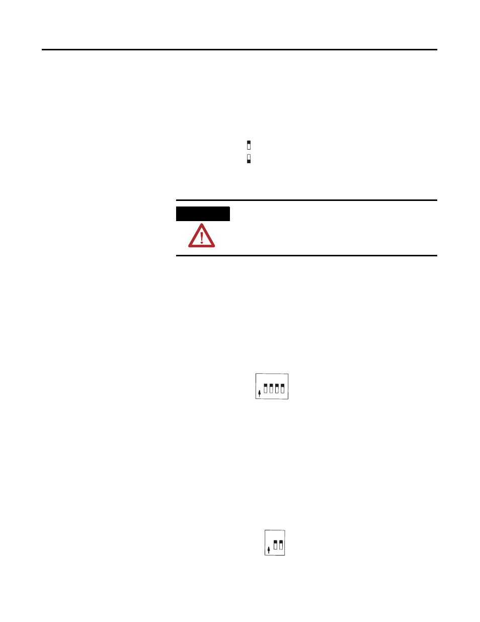
The NI4 has 4 individual DIP switches that control the input mode of
input channels 0 through 3. A switch in the ON position configures
the channel for current input. A switch in the OFF position configures
the channel for voltage input.
Switch Settings for the 1746-NIO4I and -NIO4V
The NIO4I and NIO4V have 2 individual switches labeled 1 and 2.
These switches control the input mode of input channel 0 and 1. A
switch in the ON position configures the channel for current input. A
switch in the OFF position configures the channel for voltage input.
ATTENTION
Care should be taken to avoid connecting a voltage
source to a channel configured for current input.
Improper module operation or damage to the
module can occur.
ON – Configures channel for current input
OFF – Configures channel for voltage input
1 2 3 4
N
O
Switch 1 = Channel 0
Switch 2 = Channel 1
Switch 3 = Channel 2
Switch 4 = Channel 3
Current
Voltage
1 2
N
O
Switch 1 = Channel 0
Current
Voltage
Switch 2 = Channel 1