Choosing a slot in the chassis, Installing your module – Rockwell Automation 1746-XXXX SLC 500 4-Channel Analog I/O Modules User Manual User Manual
Page 28
Publication 1746-UM005B-EN-P - June 2004
3-6 Installing and Wiring Your Analog Module
External Power Switch for the 1746-NO4I and -NO4V
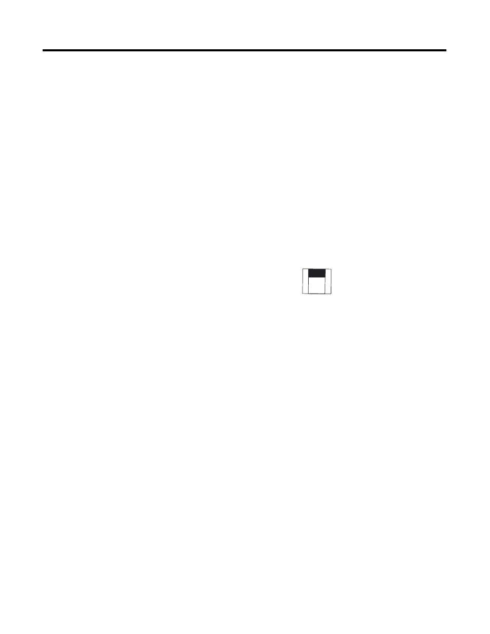
The NO4I and NO4V analog output modules have an external
24V dc power switch, SW1, which gives you the option of using an
external power supply. In the UP position, power is drawn from an
external power source. In the DOWN position, power is drawn from
the backplane of the module. The switch is located on the analog
module board. Switch orientation is also provided on the nameplate
of the module.
The 24V dc user power connection on a fixed SLC 500 can power an
NO4I or NO4V analog module. However, the regulation of the 24V dc
user connection on a modular SLC 500 power supply, Catalog Number
1746-P1, -P2, is outside of the requirements of the NO4I and NO4V
analog modules and cannot be used.
Choosing a Slot in the
Chassis
Two factors determine where the analog module should be located in
the chassis: ambient temperature and electrical noise. Consider the
following conditions when selecting a slot for an analog module.
Position the module:
•
in a slot away from ac or high voltage dc module
•
in the chassis closest to the bottom of the enclosure where the
SLC 500 system is installed
•
away from the chassis power supply if installed in a modular
system
Installing Your Module
All modules are mounted in a single slot. Remember that in a modular
system the processor always occupies the first slot of the first chassis.
When installing the analog module in a chassis, it is not necessary to
remove the terminal block from the module. However, if the terminal
block is removed, use the write-on label located on the side of the
terminal block to identify the module location and type.
Sw 1
External
Backplane
24V dc
Power
Selector