Rockwell Automation 1747-SCNR ControlNet Scanner Module Reference Manual User Manual
Page 110
Publication 1747-RM623D-EN-P - June 2006
E-32 Application Examples
The 1747-SCNR and 1747-ACNR15 modules are shown as nodes
1 and 3, respectively. The three I/O modules are under the
1747-ACNR15 in slots 1 through 3 of the 1747-ACNR15 chassis.
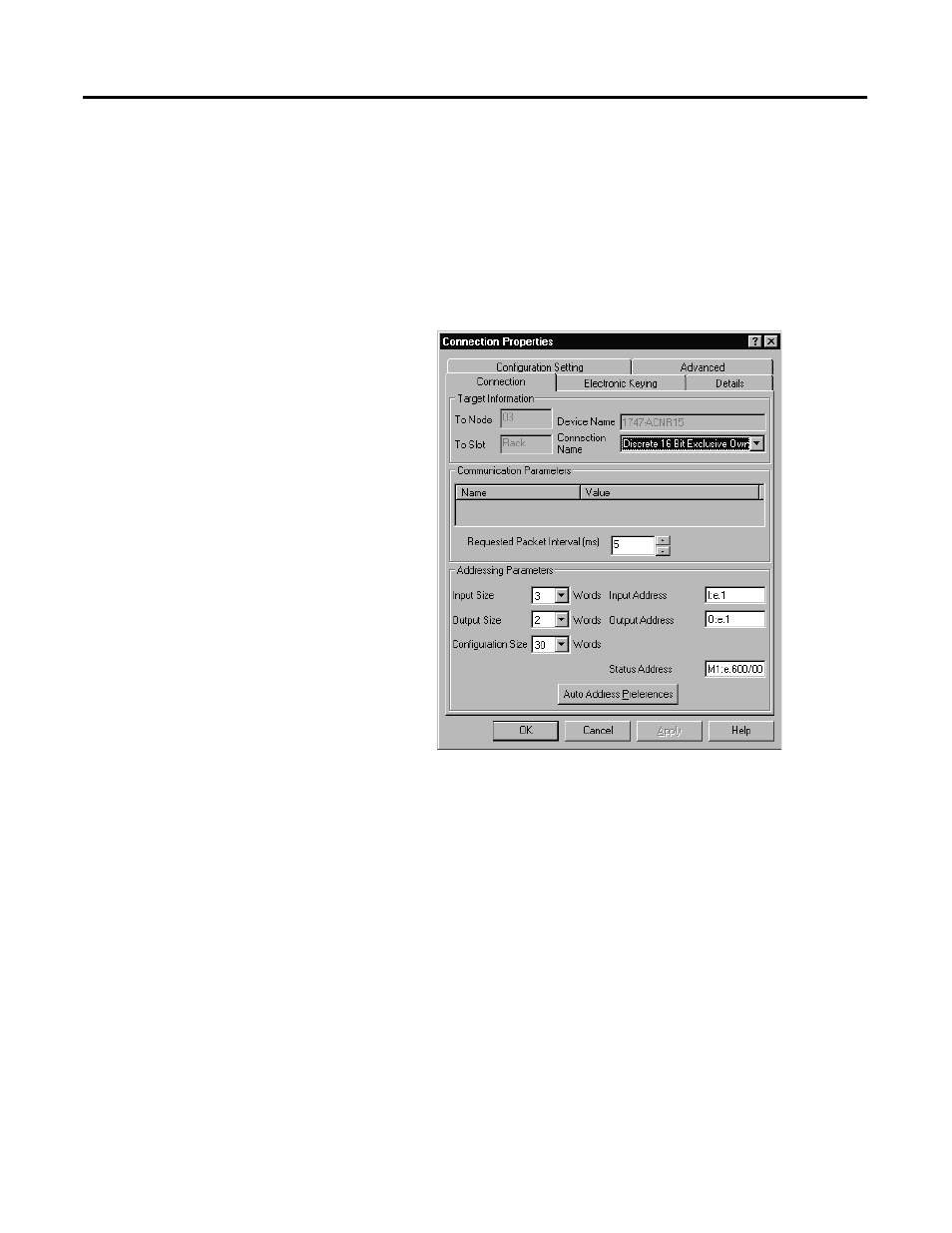
3. To establish a 16-bit rack connection to the 1747-ACNR15
chassis, right-click the 1747-ACNR15 module and choose Insert
Connection.
You see the following window:
Note that addresses in the Connection Properties window are
already displayed in the fields. To have RSNetWorx for
ControlNet software choose the next available, valid I/O or
M-file addresses for all connections:
a. Click the Auto Address Preferences button.
b. Click the box next to Enable Automatic Addressing on Insert
so that a check mark appears in the box.
c. Click OK.
The Connection Name by default is Discrete 16 Bit Exclusive
Owner. This is the 16-bit rack connection we want. The first
available I/O addresses are I:3.1 and O:3.1, where the
1747-SCNR is in slot 3 of the processor chassis. The first
available starting I/O addresses have been placed into the Input
Address and Output Address fields by RSNetWorx for ControlNet
software, because automatic addressing was previously selected
in the Auto Address Preference screen.