4 - addressing rules and examples, General, Addressing rules and examples – Rockwell Automation 1775-KA PLC-3 Communication Adapter Module User Manual User Manual
Page 57
Chapter
4
4Ć1
Addressing Rules and Examples
This chapter presents some general rules for specifying data addresses in
message procedures. This chapter assumes that you are already familiar
with the forms and meanings of addresses in the PLC–3 and other
Allen–Bradley programmable controllers. For details on these subjects,
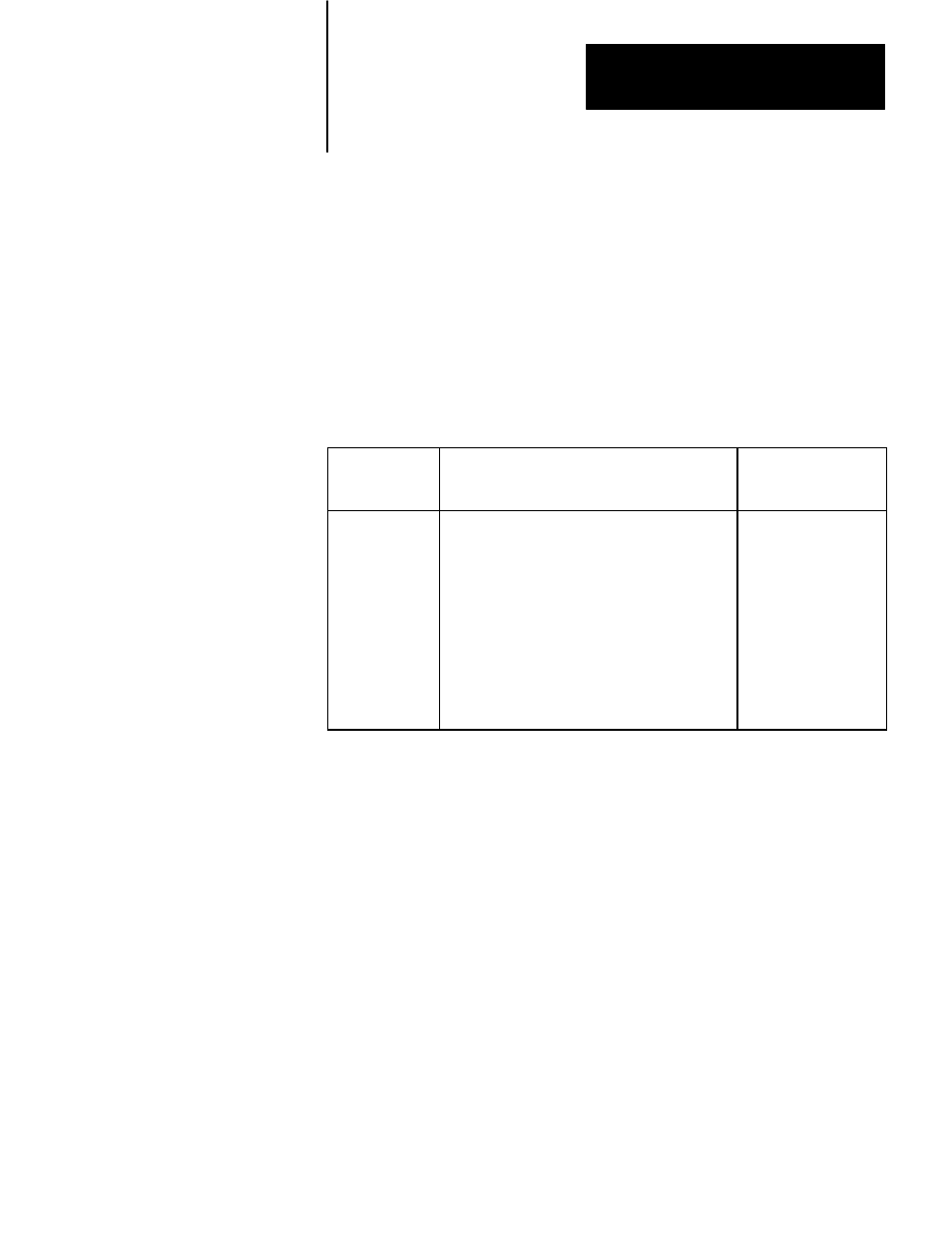
refer to the appropriate documentation listed in Table 4.A.
Table 4.A
Memory Organization Documentation
Controller
Document
Publication
Number
(Old/New No.)
PLC-3
PLC-3 Programming Manual
1775-801/1775-6.4.1
PLC
PLC Programming & Operations Manuals
1774-800/1774-6.8.1
PLC-2
PLC-2 Memory Organization and Structure
1772-907/---------
PLC-2/30
PLC-2/30 Memory Organization
1772-914/1772-4.4
PLC-2/20
Memory Organization of PLC-2.20 Controller
1772-909/1772-4.3
PLC-2/15
PLC-2/15 Memory Organization
1772-912/---------
PLC-4
PLC-4 Microtrol Product Guide
1773-800/1773-6.5.1
In this chapter,the addressing formats are presented in shorthand notation.
The notation used is as follows:
-
the number of a particular bit within the
addressed word
-
the logical address of a PLC–3 file
-
a symbolic address of a PLC–3 file
-
the number of words between the
beginning of the file and the desired word
(offset is zero for the first word of a file)
-
number of words of data to be transferred
-
the logical address of a PLC–3 word
-
a symbolic address of a PLC–3 word
General