Rockwell Automation 1775-KA PLC-3 Communication Adapter Module User Manual User Manual
Page 172
Message Formats
Appendix A
AĆ10
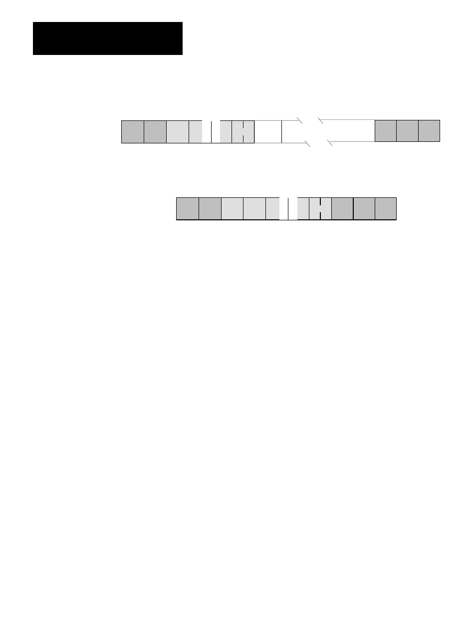
Command Format:
DLE
SRC
C
0
S
TNS
MD
0
TS
TNS ADDR
STX
DLE ETX
BCC
DATA - Max of 243 bytes
Reply Format:
DST SRC
C
S
TNS
MD T S TNS
40
DLE STX
DLE ETX
BCC
Unprotected Bit Write
Use this command to set or reset individual bits in any area of PC data
table memory. The data field in this packet consists of 4–byte blocks,
each of which contains a 16–bit address field, a set mask, and a reset
mask. Use the ADDR field to specify the address of the byte to be
modified in the PC data table memory. Put the low byte (least significant
bits) of the PC address value into the first byte of the ADDR field.
Use the SET mask to specify which bits to set to 1 in the addressed PC
byte. A1 in a bit position of the SET mask means to set the corresponding
bit in the addressed PC byte to 1; a 0 in a bit position of the SET mask
means to leave the corresponding bit in the PC byte unchanged.
Use the RESET mask to specify which bits to reset to 0 in the addressed
PC byte. A 1 in a bit position of the RESET mask means to reset the
corresponding bit in the addressed PC byte to 0; a 0 in a bit position of the
RESET mask means to leave the corresponding bit in the PC byte
unchanged.
Note that the interface module at the receiving PC station executes this
command by first making a copy of the addressed PC byte. It then sets or
resets the appropriate bits and writes the byte back into PC memory. At
the same time, the PC processor can be changing the states of the original
bits in memory. Because of this, some data bits may unintentionally be
overwritten.
Command Format: