Rockwell Automation 1775-KA PLC-3 Communication Adapter Module User Manual User Manual
Page 171
Message Formats
Appendix A
AĆ9
data table memory. Put the low byte (lest significant bits) of the PC
address value into the first byte of the ADDr field.
Use the SET mask to specify which bits to set to 1 in the addressed PC
byte. A1 in a bit position of the SET mask means to set the corresponding
bit in the addressed PC byte to 1; a 0 in a bit position of the SET mask
means to leave the corresponding bit in the PC byte unchanged.
Use the RESET mask to specify which bits to reset to 0 in the addressed
PC byte. A1 in a bit position of the RESET mask means to reset the
corresponding bit in the addressed PC byte to 0; a 0 in a bit position of the
reset mask means to leave the corresponding bit in the PC byte
unchanged.
Note that the interface module at the receiving PC station executes this
command by first making a copy of the addressed PC byte. It then sets or
resets the appropriate bits and writes the byte back into PC memory. At
the same time, the PC processor can be changing the states of the original
bits in memory. Because of this, some data bits may unintentionally be
overwritten.
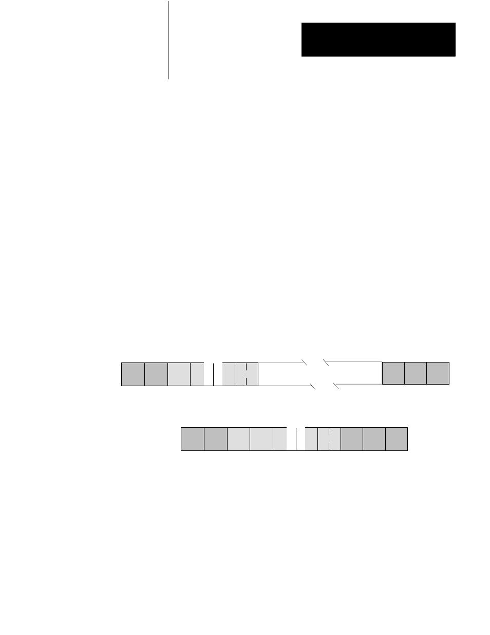
Command Format:
DLE
SRC
C
0
TNS
TNS ADDR
SET
RESET
Up to 61 masks of this form
STX
DLE ETX
BCC
S
MD
2
TS
Reply Format:
DST SRC
C
S
TNS
MD T S TNS
42
DLE STX
DLE ETX
BCC
Protected Write
Use this command to write words of data into limited areas of the PC data
table memory. Your access can be limited by memory access rungs in the
communication zone of the PC’s ladder diagram program.