Network and application layer protocols chapter 12 – Rockwell Automation 1775-KA PLC-3 Communication Adapter Module User Manual User Manual
Page 158
Network and Application Layer Protocols
Chapter 12
12Ć11
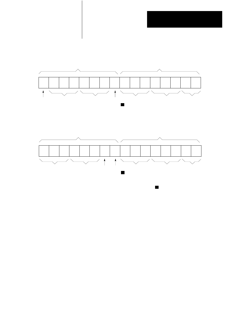
Figure 12.4
PLC/PLC-2 Data Table Byte Addressing
7
6
5
4
3
2
1
0
7
6
5
4
3
2
1
0
10065–I
Least Significant Byte
Transmitted First
Most Significant Byte
Transmitted Last
3rd
Octal
Digit
4th Octal
Digit
5th Octal
Digit
Low/
High
Byte
1st Octal
Digit
2nd Octal
Digit
3rd
Octal
Digit
a) Protected/Unprotected Read/Write ADDR Field
7
6
5
4
3
2
1
0
7
6
5
4
3
2
1
0
Least Significant Byte
Transmitted First
Most Significant Byte
Transmitted Last
3rd
Octal
Digit
4th Octal
Digit
5th Octal
Digit
Low/
High
Byte
1st Octal
Digit
2nd Octal
Digit
3rd
Octal
Digit
b) Physical Read/Write ADDR Field
1
1
1
Set this bit to 0 to select low byte of word
Since ADDR specifies an address as the number of bytes from the
beginning of PC memory, its value is double the corresponding PC word
address.
The PLC–3 logical addressing format also applies to PLC–3 type
commands. You can use this format to specify up to 6 levels of PLC–3
extended addressing. Figure 12.5 shows an example of the logical
addressing format for addressing a word in the PLC–3 data table.
The first field in the format contains a set of bit flags. Each flag is
associated with one of the levels of a PLC–3 extended address. If a flag
bit is set to 1, there must be an address specification for the corresponding
level in the address fields that follow. If a flag bit is zero, the address
fields that follow should not contain an address specification for that
level; instead, a default value is assumed.