Installing your mass storage system chapter 3 – Rockwell Automation 1770-M12 Mass Storage Systems User Manual
Page 25
Installing Your Mass Storage System
Chapter 3
3Ć10
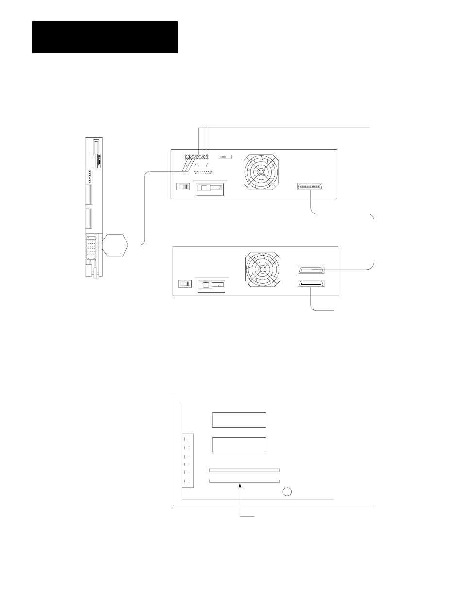
Figure 1.11
You can Connect up to Three 1770ĆM10 Systems to the Peripheral
Communication Module
Blue
Shield
Clear
11967
1775ĆGA
Peripheral
Communication
Module
1770ĆCD
Twinaxial
Cable
To another Peripheral Communication Module
1770ĆM11
Mass Storage System
1770ĆM10
Mass Storage System
To another
1770ĆM10 system
P/N 966189Ć01
Connector Cable
1.
By hand, remove the internal single inline packs (SIPs) located on the
Disk Controller Module of the 1770-M11 system. Refer to Figure 1.12.
Figure 1.12
Remove the Single Inline Packs (SIPs) Located on the Disk Controller Module
Single Inline Packs (SIPs)
11968ĆI
2.
Set the switch assembly of the 1770-M10 system to a unit number. Only
use the unit numbers 1, 2, and 3. Refer to table 3.A. for the switch
assembly settings. if you connect more than one 1770-M10 system, each