Module addressing, Appendix b, Appendix – Rockwell Automation 1769-IF4XOF2 Compact 8-Bit Low Resolution Analog I/O Combination Module User Manual
Page 73
1
Publication 1769-UM008A-EN-P - November 2001
Appendix
B
Module Addressing and Configuration with
MicroLogix 1500
This chapter examines the analog module’s addressing scheme and
describes module configuration using RSLogix 500 and MicroLogix
1500.
Module Addressing
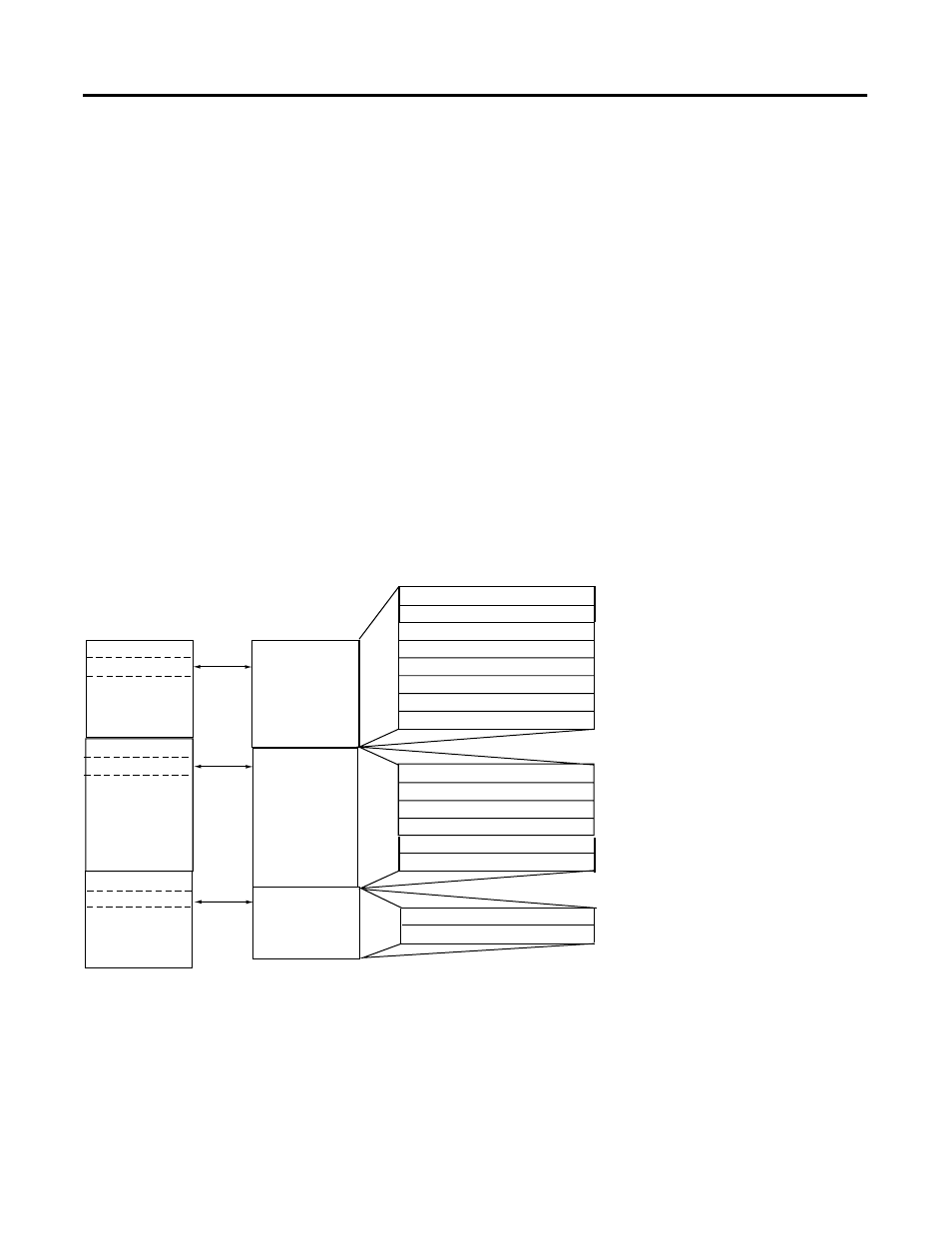
The following memory map shows the input, output, and
configuration image tables for the 1769-IF4XOF2. Detailed information
for these image tables can be found on page 4-3.
Channel 1 Input Word
Channel 2 Input Word
Over-range Bits - Inputs
Channel 3 Input Word
Over-range Bits - Outputs
Channel 0 Output Loopback
Channel 0 Input Word
Input Image
8 words
Configuration File
6 words
Output Image
2 words
slot e
slot e
slot e
Input Image File
Configuration
File
Output Image
File
Channel 1 Output Loopback
Word 0
Word 1
Word 2
Word 3
Refer to your
controller’s user
manual for
addresses.
Word 5
Word 6, bits 7 to 14
Word 7, bits 7 to 14
Output Channel 0 Fault Value
Output Channel 0 Program (Idle) Value
Output Channel 1 Fault Value
Output Channel 1 Program (Idle) Value
Channel 0 Output Data Word
Bit 15
Bit 0
Word 0
Word 1
Word 2
Word 3
Word 4
Word 5
Word 0
Word 1
Memory Map
Channel 1 Output Data Word
Configuration Word
Configuration Word
I:e.0
I:e.1
I:e.2
I:e.3
I:e.4
I:e.5
I:e.6/7 to I:e.6/14
I:e.7/7 to I:e.7/14
Address
O:e.0
O:e.1