Rockwell Automation 1769-IF4XOF2 Compact 8-Bit Low Resolution Analog I/O Combination Module User Manual
Page 33
Publication 1769-UM008A-EN-P - November 2001
Installation and Wiring 3-11
Outputs
•
Voltage outputs (Vout 0+ and Vout 1+) of the module are
referenced to ANLG COM. Load resistance for a voltage output
channel must be equal to or greater than 1K
Ω
.
•
Current outputs (Iout 0+ and Iout 1+) of the module source
current that returns to ANLG COM. Load resistance for a current
output channel must remain between 0 and 300
Ω
.
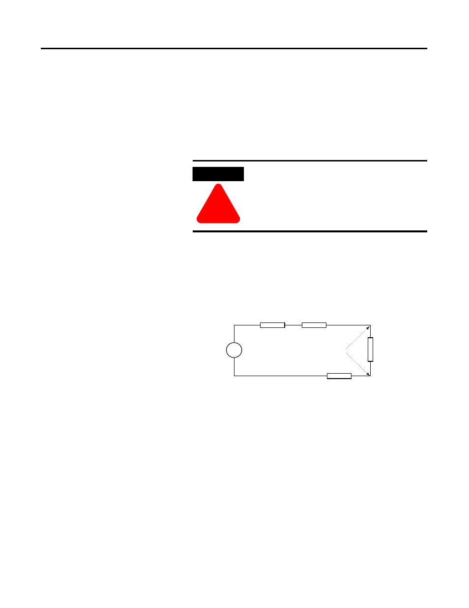
Effect of Transducer/Sensor and Cable Length Impedance on Voltage Input
Accuracy
For voltage inputs, the length of the cable used between the
transducer/sensor and the module can affect the accuracy of the data
provided by the module.
Where:
Rc = DC resistance of the cable (each conductor) depending on
cable length
Rs = Source impedance of analog transducer/sensor input
Ri = Impedance of the voltage input (150 K
Ω
)
Vs = Voltage source (voltage at the transducer/sensor input
device)
Vin = Measured potential at the module input
%Ai = Percent added inaccuracy in a voltage-based system due
to source and cable impedance.
ATTENTION
!
Be careful when stripping wires. Wire fragments
that fall into a module could cause damage at
power up. Once wiring is complete, ensure the
module is free of all metal fragments.
V in
Vs
Ri
Rc
Rc
Rs
+
-
Vin
Ri
Vs
×
[
]
Rs
2
Rc
×
(
)
Ri
+
+
[
]
-------------------------------------------------------
=