Analog input wiring, Analog input wiring -16 – Rockwell Automation 1769-IF4XOF2 Compact 8-Bit Low Resolution Analog I/O Combination Module User Manual
Page 38
Publication 1769-UM008A-EN-P - November 2001
3-16 Installation and Wiring
Wire Size and Terminal Screw Torque
Each terminal accepts up to two wires with the following restrictions:
Analog Input Wiring
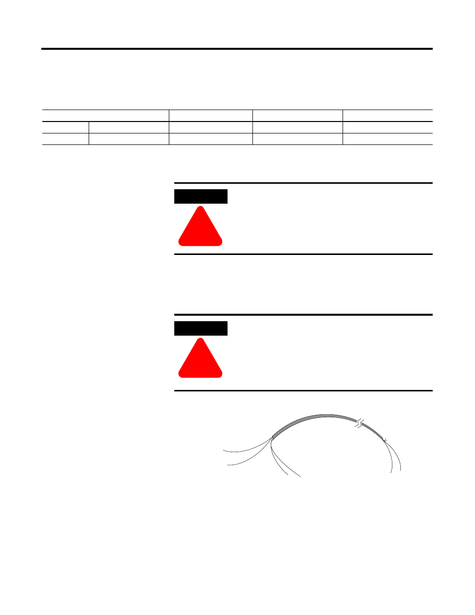
After the analog module is properly installed, follow the wiring
procedure below. To ensure proper operation and high immunity to
electrical noise, always use Belden™ 8761 (shielded, twisted-pair) or
equivalent wire.
To wire your module follow these steps.
1. At each end of the cable, strip some casing to expose the
individual wires.
2. Trim the signal wires to 2-inch lengths. Strip about 3/16 inch (5
mm) of insulation away to expose the end of the wire.
Wire Type
Wire Size
Terminal Screw Torque
Retaining Screw Torque
Solid
Cu-90°C (194°F)
#14 to #22 AWG
0.68 Nm (6 in-lbs)
0.46 Nm (4.1 in-lbs)
Stranded
Cu-90°C (194°F)
#16 to #22 AWG
0.68 Nm (6 in-lbs)
0.46 Nm (4.1 in-lbs)
ATTENTION
!
To prevent shock hazard, care should be taken when
wiring the module to analog signal sources. Before
wiring any analog module, disconnect power from
the system power supply and from any other source
to the analog module.
ATTENTION
!
When wiring an analog input, take care to avoid
connecting a voltage source to a channel configured
for current input. Improper module operation or
damage to the voltage source can occur.
Never connect a voltage or current source to an
analog output channel.
cable
signal wire
signal wire
drain wire
foil shield
signal wire
signal wire
Cut foil shield
and drain wire