Analog range selection, Valid input data word formats/ranges – Rockwell Automation 1769-IF4XOF2 Compact 8-Bit Low Resolution Analog I/O Combination Module User Manual
Page 58
Publication 1769-UM008A-EN-P - November 2001
4-14 1769-IF4XOF2 Module Data, Status, and Configuration Channels
Analog Range Selection
The analog input range selection is accomplished by proper wiring of
the input channels.
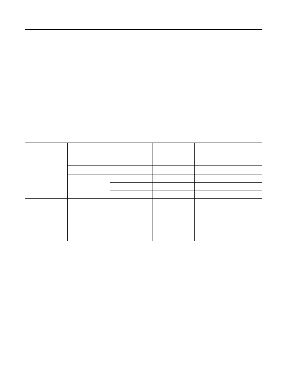
Valid Input Data Word Formats/Ranges
The analog input data received at the module is converted to
RAW/proportional data format. Unlike the 1769-IF4 and 1769OF2.
on-board scaling is not provided by the module. You must do this via
your control program.
The following table shows the valid input data format for the data
range provided by the module.
Table 4.9 Valid Input Data
Input Range
Input Value
Example Data
Input Range
Condition
Raw/Proportional Data
Decimal Range
0 to +10V dc
Over 10.5V dc
+11.0V dc
Over-range
(1)
(1) The module’s maximum range is 10.5V or 21 mA. An over-range flag is set at either value. This flag automatically resets when the input data is below the over-range value.
32640
+10.5V dc
+ 10.5V dc
Over-range
32640
0.0V dc to
+10.0V dc
+10.0V dc
Normal
31104
5.0V dc
Normal
15488
0.0V dc
Normal
0
0 to 20 mA
Over 21.0 mA
+22.0 mA
Over-range
32640
21.0 mA
+21.0 mA
Over-range
32640
0.0 mA to 20.0 mA
+20.0 mA
Normal
31104
+10.0 mA
Normal
15488
0.0 mA
Normal
0