Module addressing, Chapter 4, Module addressing -1 – Rockwell Automation 1769-IF4XOF2 Compact 8-Bit Low Resolution Analog I/O Combination Module User Manual
Page 45: Chapter
1
Publication 1769-UM008A-EN-P - November 2001
Chapter
4
1769-IF4XOF2 Module Data, Status, and
Configuration Channels
This chapter examines the 1769-IF4XOF2 module’s data table, channel
status, and channel configuration word:
•
•
•
•
Configuration Data File on page 4-8
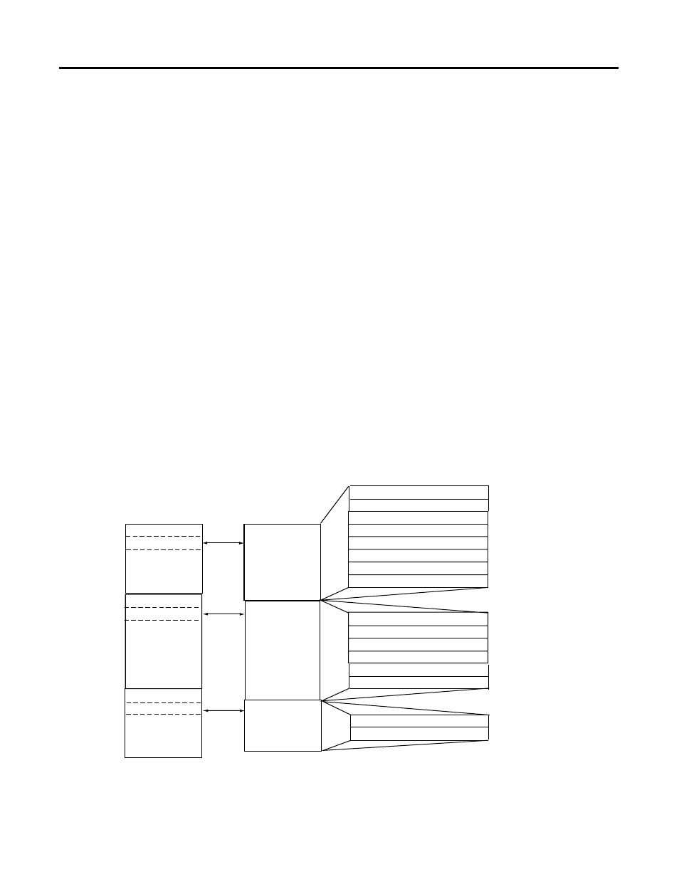
Module Addressing
The following memory map shows the input, output, and
configuration image tables. Detailed information on the input image
table can be found in Input Image on page 4-3.
Channel 1 Input Word
Channel 2 Input Word
Over-range Bits - Inputs
Channel 3 Input Word
Over-range Bits - Outputs
Channel 0 Output Loopback
Channel 0 Input Word
Input Image
8 words
Configuration File
6 words
Output Image
2 words
slot e
slot e
slot e
Input Image File
Configuration
File
Output Image
File
Channel 1 Output Loopback
Word 0
Word 1
Word 2
Word 3
Word 4
Word 5
Word 6, bits 7 to 14
Word 7, bits 7 to 14
Output Channel 0 Fault Value
Output Channel 0 Program (Idle) Value
Output Channel 1 Fault Value
Output Channel 1 Program (Idle) Value
Channel 0 Output Data Word
Bit 15
Bit 0
Word 0
Word 1
Word 2
Word 3
Word 4
Word 5
Word 0
Word 1
Memory Map
Channel 1 Output Data Word
Configuration Word
Configuration Word