Examples of period/rate and continuous/rate – Rockwell Automation 1771-VHSC , D17716.5.74 Very High S User Manual
Page 76
Period/Rate and Continuous/Rate Examples
E–5
The 4MHz count, total count, frequency and new data bit reported to
the programmable controller will be updated every scaler number of
pulses. And 250–260ms after the last pulses stop, the 4MHz count
will go to 999,999, the frequency will go to 0 and the new data bit
will be set. The outputs are updated dynamically on the module as
the 4MHz count increases.
If less than the scaler number of pulses occurs in 250ms, but at least
1/2(scaler) + 1 pulses occur in 250ms, the operation of 4MHz count
and frequency will be accurate, but may appear intermittent due to
“left over” pulses. The outputs will always update every scaler
number of pulses regardless of the update of the 4MHz count.
Note: “Left over” pulses are pulses that occur that are not divisible
by the scaler. (i.e. With a scaler of 4, if 6 pulses occur there are 2
“left over” pulses.)
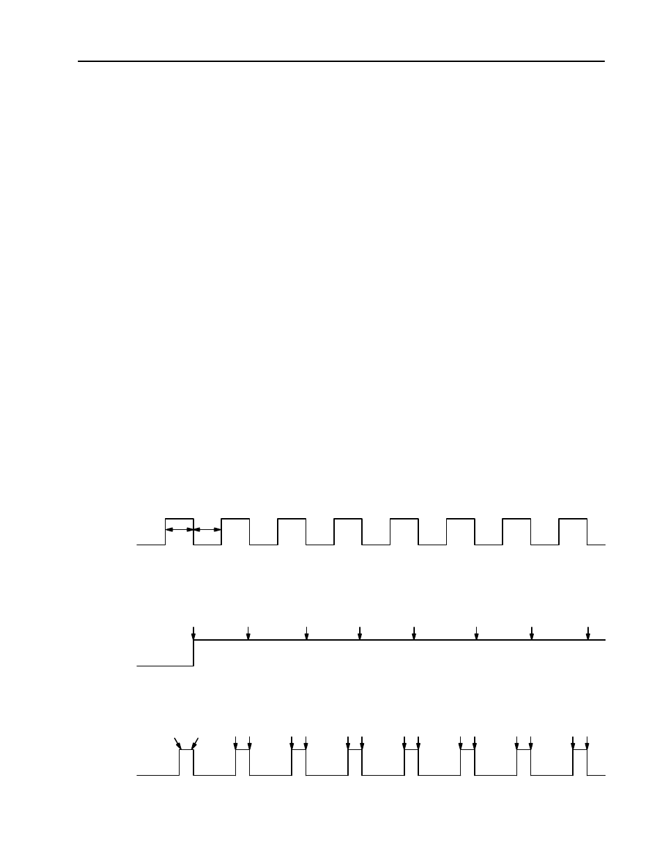
The following waveforms illustrate the difference between period/rate
and continuous/rate. All waveforms were initiated by applying a 50Hz
signal at the gate/reset terminal of a counter configured for either
period/rate or continuous/rate. The output configuration remained
constant with an ON value of 20,000 counts and an OFF value of
80,000 counts. Only the scalar mode was varied to show the operation
of the two modes.
Figure E.1
Operation of Outputs in Period/Rate and Continuous/Rate with
Scaler = 1
50Hz at Gate/Reset
50% Duty Cycle
Scaler = 1
Counter times
width of pulse
4MHz count = 40,000
Counter
Idle
CHANNEL IN PERIOD/RATE
CHANNEL IN CONTINUOUS/RATE
ON at 20,000
OFF at 80,000
Scaler = 1
ON at 20,000
OFF at 80,000
Scaler = 1
4MHz Count
= 40,000
4MHz Count = 40,000
4MHz Count
= 20,000
Examples of Period/Rate and
Continuous/Rate