Plc 2 program example, Plcć2 program example – Rockwell Automation 1771-VHSC , D17716.5.74 Very High S User Manual
Page 36
3–2
Module Programming
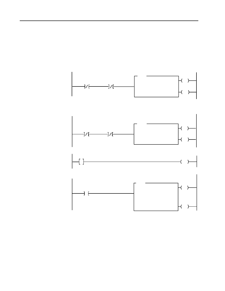
Figure 3.1 below shows a sample PLC-2 program.
Figure 3.1
PLCĆ2 Family Sample Program Structure
EN
FILE TO FILE MOVE
COUNTER ADDR:
POSITION:
FILE LENGTH:
FILE A:
033
1
18
301-322
DN
FILE R:
RATE PER SCAN:
331-352
18
07
17
15
4
110
033
033
EN
DN
06
110
010
110
06
06
2
EN
BLOCK TRANSFER READ
DATA ADDRESS:
MODULE ADDRESS:
BLOCK LENGTH:
030
100
00
DN
FILE:
301-400
07
110
010
110
07
07
1
BTR
BLOCK TRANSFER WRITE
DATA ADDRESS:
MODULE ADDRESS:
BLOCK LENGTH:
031
100
00
FILE:
201-300
PUT
032
G
032
0
0
3
BTW
FFM
The VHSC module is located in rack 1, module group 0, slot 0. The data address 030 is among the first available timer/counters used for block transfer.
The default block length of 0 results in a 18 word block transfer read. The module status data is returned to the processor starting at address 301.
If a block length other than 0 is specified for the BTR or BTW the BTR and BTW cannot be enabled during the scan.
VHSC BTR Data Address
VHSC BTR
Done Bit
VHSC BTW
Enable Bit
06
010
The VHSC module is located in rack 1, module group 0, slot 0. The data address 031 is among the first available timer/counters used for block transfer.
The default block length of 0 results in a 64 word block transfer write. The module configuration data is stored starting at address 201. The preconditions
could also include the configuration bit (word 1, bit 0) to limit the block transfer write.
VHSC BTW
Done Bit
VHSC BTR
Enable Bit
07
010
This rung is used to place a zero between the first available timer counters used for all block transfers and those used throughout the rest of
the program.
This rung uses a BTR done bit to trigger a move of the count data stored at 301 to a buffered location at 331. The program should access all data
from the buffered file (count 0 MSD would be located in word 333 and the LSD in word 334.)
VHSC BTR
Done Bit
PLCĆ2 Program Example