Plc 5 program example, Plcć5 program example – Rockwell Automation 1771-VHSC , D17716.5.74 Very High S User Manual
Page 38
3–4
Module Programming
Block transfer instructions with the PLC-5 processor use one binary
file in a data table section for module location and other related data.
This is the block transfer control file. The block transfer data file
stores data that you want transferred to the module (when
programming a block transfer write) or from the module (when
programming a block transfer read). The address of the block
transfer data files are stored in the block transfer control file.
The industrial terminal prompts you to create a control file when a
block transfer instruction is being programmed. A different block
transfer control file is used for the read and write instructions
for your module.
Figure 3.3
PLCĆ5 Family Sample Program Structure
EN
BTR
BLOCK XFER READ
RACK:
GROUP:
MODULE:
CONTROL:
0
0
0
N21:0
DN
DATA FILE:
LENGTH:
CONTINUOUS:
N22:101
0
N
ER
EN
BTW
BLOCK XFER WRITE
RACK:
GROUP:
MODULE:
CONTROL:
0
0
0
N21:5
DN
DATA FILE:
LENGTH:
CONTINUOUS:
N22:1
0
N
ER
N21:0
15
N21:0
15
N21:5
15
1
2
The VHSC module is located in rack 0, module group 0, slot 0. The BTR control file starts at N21:0 and is 5 words long. The data obtained by the
processor from the VHSC is placed in memory starting at location N22:101, and with the default length of 0 is 18 words long. The MSD of counter
0 is stored in N22:103 and the LSD of counter 0 is stored in N22:104.
N21:5
15
The VHSC module is located in rack 0, module group 0, slot 0. The BTWcontrol file starts at N21:5 and is a 5 words long.
The data sent by the processor to the VHSC is stored in memory starting at location N22:1, and with the default length of 0 is 64 words long.
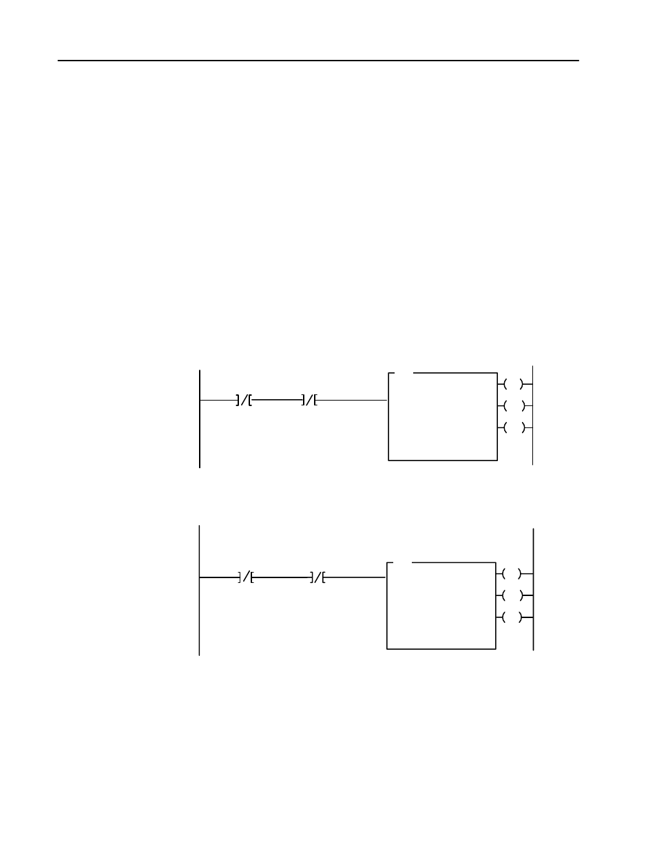
VHSC BTR
Enable Bit
VHSC BTW
Enable Bit
VHSC BTR
Control File
VHSC BTR
Enable Bit
VHSC BTW
Enable Bit
VHSC BTW
Control File
PLCĆ5 Program Example