12 to +24v singlećended driver, Application considerations c–5, Input terminals – Rockwell Automation 1771-VHSC , D17716.5.74 Very High S User Manual
Page 62
Application Considerations
C–5
+12 to +24V SingleĆEnded Driver
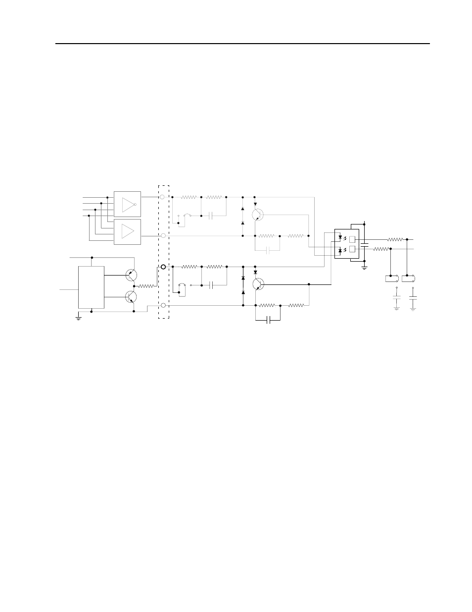
Some European-made encoders use a circuit similar to the lower
circuit in Figure C.2. The current capable of being sourced is limited
only by the 22 ohm resistor in the driver output circuit (R). If a 24
volt supply is used, and this driver supplies 15mA, the output voltage
would still be about 23V (15mA x 22 ohms = 0.33V, and Vce = .7V).
Figure C.2
Example Circuits for 5V Differential and +12 to +24V SingleĆEnded Drivers
R1
R2
C41
JPR4 JPR5
JPR6
JPR7
JPR8 JPR9
JPR10
JPR11
R3
R4
R97
R98
C43
Q2
Q3
D2
D3
D5
D6
R100
R101
R31
R36
C38
C42
+5V
C3
C4
1
2
3
4
5V DIFFERENTIAL
LINE DRIVER
+12 TO 24V
INPUT
HIGH
LOW
DRIVE
DRIVE
+12 TO 24V
SINGLEĆENDED
DRIVER
150
1K
R
150
1K
22 ohm
Input Terminals
Voltage Jumpers
Voltage Jumpers
Filter Jumpers
10691ĆI
Drive
Circuit
D1
D4
40.2
40.2
40.2
40.2
If the input jumper is in position JPR8, the current to the photodiode
is limited by the series resistance of R3 and R4 (about 1.15Kohms).
A protection circuit consisting of Q3, R100 and R101 is included. If
the current through the photodiode exceeds about 8mA, the voltage
across R100 and R101 is sufficient to turn Q3 on, shunting any
additional current away from the photodiode. The voltage drop
across Q3 will be equal to about 2V (Vphotodiode + Vbe = 2V). The
current demanded by the 1771-VHSC input circuit would be about
18mA (23V - 2V/1.15K = 18mA) which is well within the capability
of this driver.