Plc 3 program example, Plcć3 program example – Rockwell Automation 1771-VHSC , D17716.5.74 Very High S User Manual
Page 37
3–3
Module Programming
Block transfer instructions with the PLC-3 processor use one binary
file in a data table section for module location and other related data.
This is the block transfer control file. The block transfer data file
stores data that you want transferred to the module (when
programming a block transfer write) or from the module (when
programming a block transfer read). The address of the block
transfer data files are stored in the block transfer control file.
The industrial terminal prompts you to create a control file when a
block transfer instruction is being programmed. The same block
transfer control file is used for both the read and write
instructions for your module. A different block transfer control file
is required for every module.
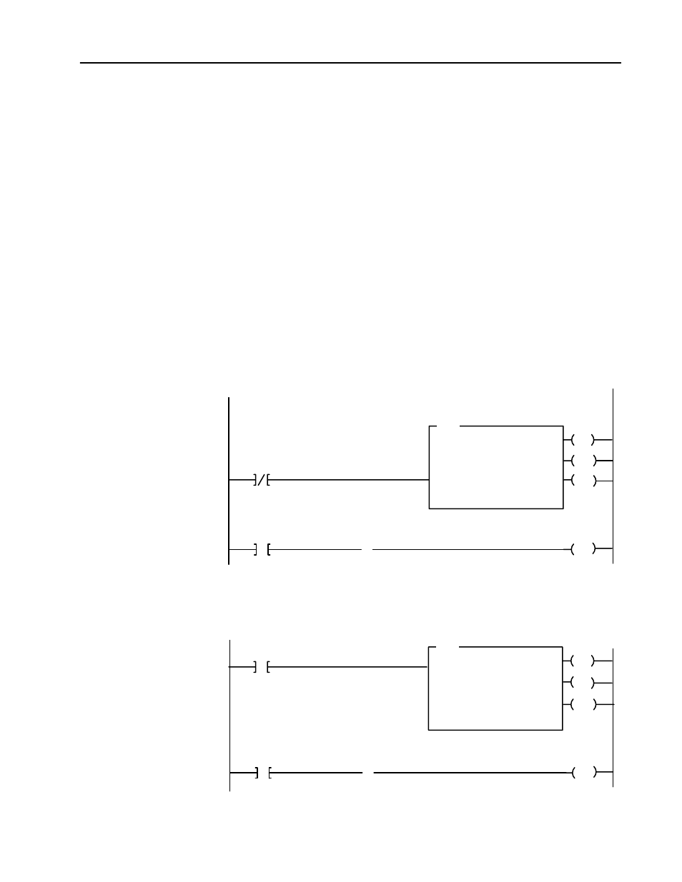
A sample program is shown in Figure 3.2 below.
Figure 3.2
PLCĆ3 Family Sample Program Structure
EN
BTR
BLOCK XFER READ
RACK:
GROUP:
MODULE:
DATA:
1
0
0
N13:101
LENGTH:
CNTL:
0
B12:0
EN
BTW
BLOCK XFER WRITE
RACK:
GROUP:
,MODULE:
DATA:
1
0
0
N13:1
DN
LENGTH:
CNTL:
0
B12:0
5
B12:0
B12:0
15
ER
DN
ER
The VHSC module is located in rack 1, module group 0, slot 0. The control file is a 10 word file, shared by the BTR and BTW, starting at B12:0.
The data obtained by the processor from the VHSC is placed in memory starting at location N13:101, and with the default length of 0 is 18 words
long. The MSD of counter 0 is stored in N13:103 and the LSD of counter 0 is stored in N13:104.
VHSC BTR
Done Bit
VHSC BTR/BTW
Control Block
The VHSC module is located in rack 1, module group 0, slot 0. The control file is a 10 word file, shared by the BTR and BTW, starting at B12:0.
The data sent by the processor to the VHSC is placed in memory starting at location N13:1, and with the default length of 0 is 64 words long. If the
default mode of VHSC operation is desired (rollover at 999,999 outputs disabled), this rung can be optional. The module configured bit can also
be used as a precondition to increase BTR throughput.
13
B12:0
13
U
VHSC BTR
Error Bit
VHSC BTR
Error Bit
B12:0
VHSC BTW
Done Bit
VHSC BTR/BTW
Control Block
3
B12:0
3
B12:0
U
VHSC BTW
Error Bit
VHSC BTW
Error Bit
PLCĆ3 Program Example