Interpreting the indicator lights, Chapter summary, Interpreting the indicator lights chapter summary – Rockwell Automation 1771-VHSC , D17716.5.74 Very High S User Manual
Page 34
2–8
Installing the Very High-Speed Counter Module
4. Snap the chassis latch over the top of the module to secure it.
5. Connect the wiring arm to the module.
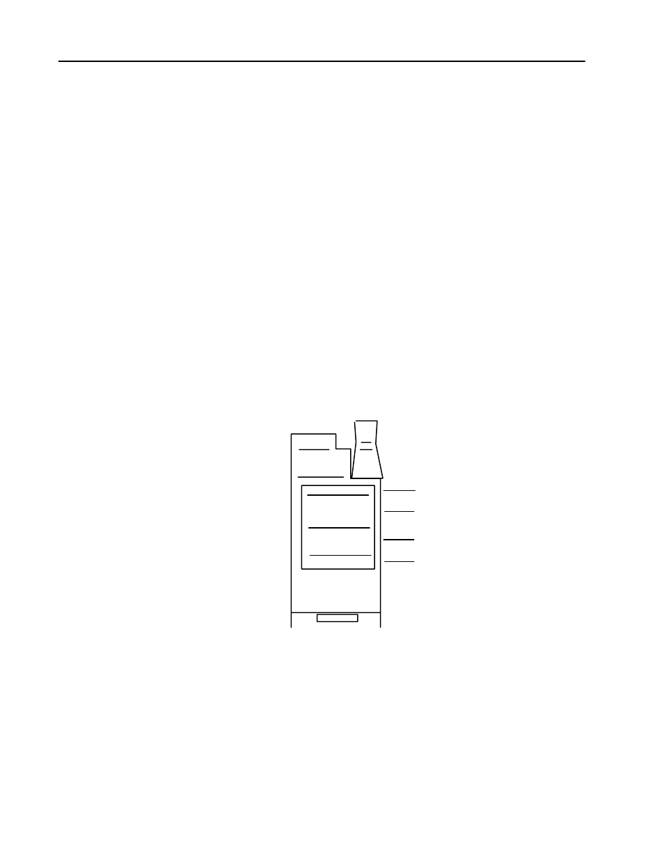
The front panel of the input module contains 12 input indicators, 8
output indicators, an active indicator and a fault indicator
(Figure 2.5). At power-up, the active and fault indicators are on. An
initial module self-check occurs. If there is no fault, the red indicator
turns off. If a fault is found initially or occurs later, the fault indicator
lights and the active indicator is forced off.
When an input LED (A, B) is on, it indicates that the input is high.
When the output LED is on, it indicates that the module has
commanded the output to be on. When a gate/reset indicator (G) is
on, its input is high. Since that signal can be inverted, it does not
indicate whether the signal on that terminal is necessarily logically
true.
Possible module fault causes and corrective action are discussed in
the chapter titled “Troubleshooting.”
Figure 2.5
Diagnostic Indicators
A0 A1 A2 A3
B0 B1 B2 B3
00 02 04 06
01 03 05 07
ACTIVE
INPUTS
FAULT
OUTPUTS
Input Indicators
Output Indicators
Fault Indicator
Active Indicator
G0 G1 G2 G3
10690ĆI
In this chapter you learned how to install your input module in an
existing programmable controller system and how to wire to the field
wiring arm.
Interpreting the Indicator
Lights
Chapter Summary