Bit/word descriptions – Rockwell Automation 1771-VHSC , D17716.5.74 Very High S User Manual
Page 42
4–3
Configuring Your Module
00
01
02
03
04
05
06
07
08
09
10
11
12
13
14
15
Word
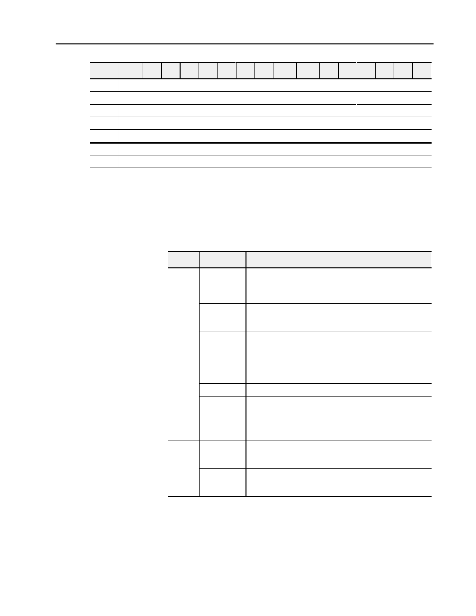
34
Output 1 Off LSD
Words repeat for each additional output: 35Ć39 output 2, 40Ć44 output 3, 45Ć49 output 4, 50Ć54 output 5, 55Ć59 output 6
60
Not used
Tie Output 7 to Counter
61
Output 7 On MSD
62
Output 7 On LSD
63
Output 7 Off MSD
64
Output 7 Off LSD
Bit/word descriptions of BTW file words are presented in Table 4.B.
Enter data into the BTW instruction after entering the instruction into
your ladder diagram program.
Table 4.B
Bit/Word Definitions for the VHSC Module
Word
Bits
Description
Word 1
bits 00Ć03
These bits control the reset function. When one of these bits
transitions from 0 to 1, the counter is reset to 0 and begins counting.
The bits correspond to the 4 counters: bit 00 = counter 0; bit 01 =
counter 1; bit 02 = counter 2; bit 03 = counter 3.
bits 04Ć07
New data acknowledge bits. When one of these bits transitions from 0
to 1 the corresponding new data bit in BTR word 1, bits 4Ć7 will be
reset. Bit 04 corresponds to counter 0, bit 05 to counter 1, etc.
bits 08Ć11
These bits control the preset function. When one of these bits is set to
1, the preset count value is automatically loaded into the counter and
the counter begins counting. (Note: The preset count values are
loaded into words 13 through 20.) The bits correspond to the counters
as follows: Bit 08 = counter 0; bit 09 = counter 1; bit 10 = counter 2; bit
11 = counter 3.
bits 12Ć14
Not used
bit 15
This bit determines whether BCD or binary format is used.
Bit 15 = 0 Indicates all values in the BTW file and the BTR file will be
in binary. (Diagnostic byte (word 1) is always BCD.)
Bit 15 = 1 Indicates all values in the BTW file and the BTR file will be
in BCD.
Word 2
bits 00Ć07
Enables outputs. Bit 00 corresponds to output 0, bit 01 to output 1,
etc. Outputs must be enabled before they can be turned ON. Bits
must be set (1) before the output can be turned on.
bits 08Ć15
Output forcing bits. Setting a bit to 1 allows the output to be forced. Bit
08 corresponds to output 0, bit 09 corresponds to output 1, etc.
Outputs must also be enabled.
Bit/Word Descriptions