Power wiring – Rockwell Automation 1305 AC Drive, Firmware 1.01-3.00 User Manual User Manual
Page 27
Chapter 2 – Installation/Wiring
2-11
POWER WIRING
Input and output power connections are performed through a
ten position terminal block, TB1 (see page 2-3 for location).
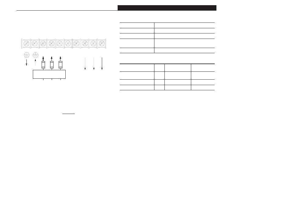
Figure 2.6 Power Terminal Block Designations (TB1)
GND
GND
L1
R
L2
S
L3
T
+DC BRK➀
(-DC)
T1
U
T2
V
T3
W
Required Branch
Circuit Disconnect
AC Input Line
To Motor
➀
Connection for Dynamic Brake Resistors for all models except the 200-230 Volt,
0.37 to 0.75 kW (1/2 to 1 HP) drive. IMPORTANT: The [DB Enable] parameter must
be enabled for proper operation.
➁
For single phase applications, the AC input line can be connected to any two of
the three input terminals R, S, T (L1, L2, L3).
➂
Bulletin 1305 drives are UL listed and CSA certified as a motor overload protec-
tive device. An external overload relay is not required for single motor applications.
IMPORTANT: This drive is not intended for use with single phase motors.
➃
Ground from drive to motor frame must be an independent continuous insulated
wire run.
To
Motor
➃
Required
Input Fusing
➁
➂
Table 2.B Power Block Terminal (TB1)
Terminals
Description
GND
Earth Ground
R, S, T (L1, L2, L3)
AC Input Line Terminals
+DC, BRK (or -DC)
Dynamic Brake Option - Refer to instructions included
with option
U, V, W (T1, T2, T3)
Motor Connection
Table 2.C Screw Size, Wire Size and Torque Specifications
Terminal
Screw
Size
Max./Min. Wire Size
mm
2
(AWG
)
Maximum Torque
N-m ( lb-ins. )
TB1
(0.37 to 0.75kW/1/2 to 1 HP)
M4
3.5/0.75 (12/18)
0.90 (8)
TB1 (All except above)
M4
4/0.75 (10/18)
1.81 (16)
TB2 (All)
M3.5
1.5/0.20 (14/24)
0.90 (8)