Rockwell Automation 1402-LSM Line Synchronization Module Installation Instructions User Manual
Page 55
I/O Definition
Appendix B
Block Transfer and Discrete
B–7
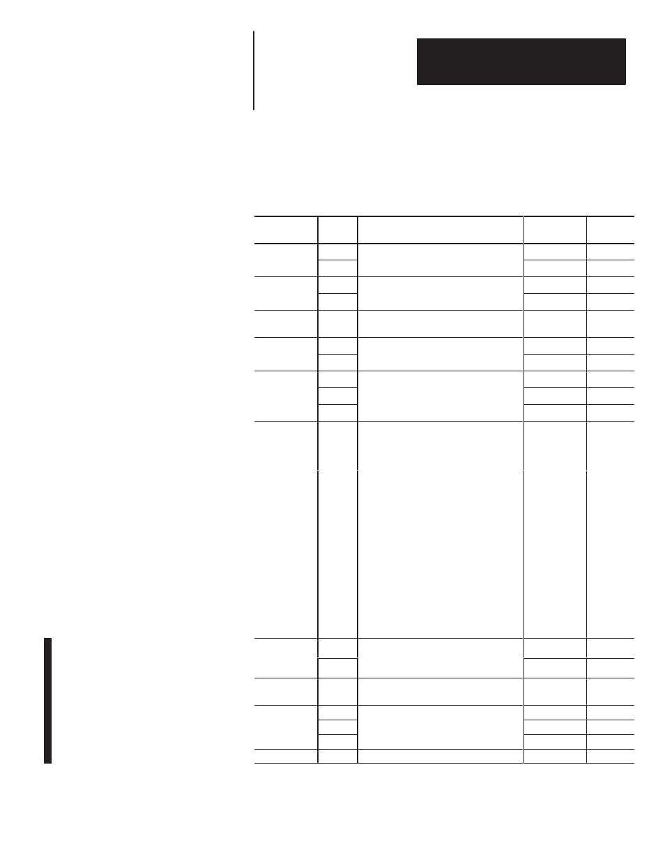
Table B.6
Synchronizing Bus Error Parameters
Parameter
Number
Word
Number
Description
Range
Modulus
1
1
Voltage Match Error in Percent
±
0 – 999
10
–3
1
2
V
(Step Size of 0.05 %)
±
0 – 100
10
0
2
3
Frequency Match Error in Hz
±
0 – 999
10
–3
2
4
(Step Size of 0.01 Hz)
±
0 – 99
10
0
3
5
Synchronizing Bus to Reference Bus
Phase Match Error in Degrees
±
0 to 180
10
0
4
6
±
0 – 999
10
–3
4
7
Load Sharing Error
±
0 – 1
10
0
8
±
0 – 999
10
0
5
9
Power in Watts – Total
±
0 – 999
10
3
10
±
0 – 999
10
6
Synchronization Status
Bit 0 Frequency Within Limits
Bit 1 Voltage Within Limits
2
Bit 2 Phase Within Limits
3
Bit 3 Synchronization Mode Conflict Failure
4
Bit 4 Phase Rotation Mismatch Failure
6
11
Bit 5 Reserved for Product Expansion
V
Sixteen Bits
–––
11
Bit 6 No Reference Bus Voltage Present
Failure
Bit 7 Synchronizing Bus No Voltage
Present Failure
Bit 8 Reference Bus Overvoltage Failure
9
Bit 9 Synchronizing Bus
Overvoltage Failure
Bit 10 – Bit 15 Reserved
7
12
Synchronizing Bus Average Voltage L–L in
V
0–999
10
0
7
13
Volts
(same as parameter 15 in Table B.7)
0–999
10
3
8
14
Power Factor in Percent – Total
(same as parameter 1 in Table B.8)
±
0–100
10
0
15
V
±
0–999
10
0
9
16
Reactive Power in VAR – Total
13
±
0–999
10
3
9
17
(same as parameter 13 in Table B.8)
±
0–999
10
6
10
18
Reserved for Product Expansion
—
—