Ladder program description continued, Data files used – Rockwell Automation 1402-LSM Line Synchronization Module Installation Instructions User Manual
Page 43
Chapter 4
Application Information
4–9
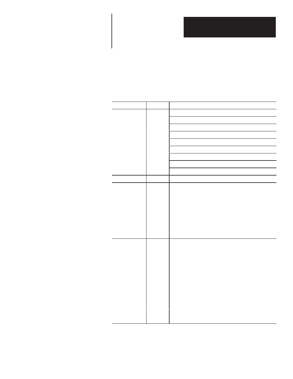
Data Files Used
Table 4.4
Data File
Data
Description
b3/0 Internal Trigger
b3/1 Config Mode Enable
b3/2 Data Reset
b3/3 Run mode Sequence Complete
B3
b3/4 Valid Config Data
B
b3/5 Config Sequence Complete/Data Valid
b3/6 Module Config Complete
b3/9 One–shot bit
b3/10 One–shot bit
N10
n10:0 Sequencer output (BT select word)
N21
Config mode sequencer input file.
For proper configuration with the sequencer at rung 2:7 set to a
length of 4 words, the following data MUST be in file N21.
N21:0
59
D Factory Configuration Parameters
N21:1
59
D Factory Configuration Parameters
N21:2
52
D Factory Acknowledge Configuration
N21:3
60
D User Configuration Parameters
N21:4
53
D User Acknowledge Configuration Parameters
N22
Run mode sequencer input file
For proper configuration with the sequencer at rung 2:8 set to a
length of 8 words, the following data MUST be in file N22.
N22:0
54
D Synchronizing Bus Error Parameters
N22:1
54
D Synchronizing Bus Error Parameters
N22:2
50
D Factory Configuration Parameters
N22:3
51
D User Configuration Parameters
N22:4
55
D Synchronizing Bus Voltage/Current Parameters
N22:5
54
D Synchronizing Bus Errors
N22:6
56
D Synchronizing Bus Power Parameters
N22:7
57
D Reference Bus Voltage Parameters
N22:8
58
D Diagnostic Parameters
Ladder Program Description
Continued