Interfacing to the lsm continued – Rockwell Automation 1402-LSM Line Synchronization Module Installation Instructions User Manual
Page 38
Chapter 4
Application Information
4–4
Acquiring Data From the LSM
The data from the LSM is returned in four tables. These tables are again
differentiated by the size/ID of the BTR instruction. These tables are
Synchronizing Bus Error Parameters, Synchronizing Bus Voltage/Current
Parameters, Synchronizing Bus Power Parameters, and Reference Bus
Voltage Parameters. The sizes and contents of these tables are provided in
Appendix B of this document.
To acquire the table Synchronizing Bus Error Parameters from the LSM, the
PLC–5 must issue a BTR instruction with the size of this table. The data file
entry of the BTR is where the table from the LSM will be placed. Any
operations using this data must then be directed to this file within the PLC–5.
Discrete Input / Output Control of the LSM
The LSM uses both discrete outputs from the PLC–5 and inputs to the
PLC–5 in addition to its block transfer capabilities.
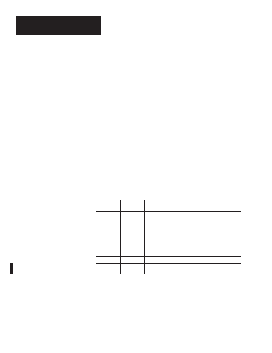
Discrete Outputs From The PLC–5
The discrete outputs from the PLC–5 to the LSM are as follows:
Table 4.2
Octal Bit
Number
Decimal Bit
Number
Output Description
State Values
17
15
Initiate Synchronization
1 = Initiate
16
14
Auto–Synchronization Mode
1 = Assert this mode
15
13
Check Synchronization Mode
1 = Assert this mode
14
12
Permissive Synchronization
Mode
1 = Assert this mode
13
11
Load Share Disable
1 = Disable Load Share
12
10
Isochronous/Droop Mode
1 = Isochronous Mode
11
9
Unused
N/A
10
8
Enable Single Phase Syn-
chronization
1 = Single Phase
0 = 3-Phase
The Initiate Synchronization output from the PLC–5 controls the operation
mode of the LSM. This output from the PLC–5 operates as shown in
Table 4.1 on Page 4–1.
The Auto Synchronization Mode output from the PLC–5, Check
Synchronization Mode output from the PLC–5, and the Permissive
Synchronization Mode output from the PLC–5 are only used when the
module is in a Synchronization mode (i.e. the Initiate Synchronization output
from the PLC–5 is set). Only one of these Synchronization Mode outputs
from the PLC–5 may be set at one time. If more than one of those signals is
Interfacing to the LSM Continued