Rockwell Automation 1395 Digital Reference Adapter Board User Manual
Page 57
Chapter 6
StartĆUp
6-11
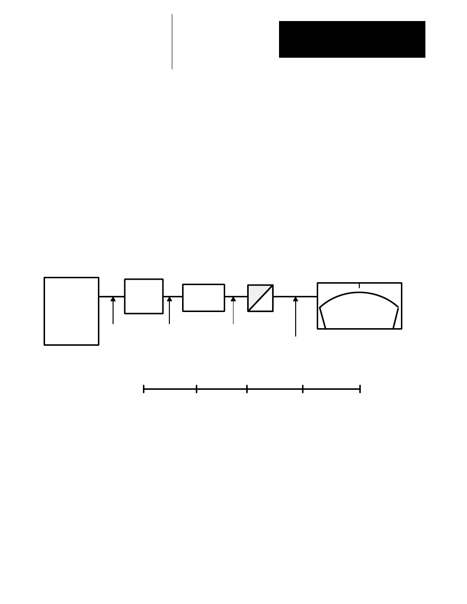
As was shown previously, another 0 to 10 VDC meter is connected to
Digital-To-Analog (D/A) output number 2. In this example, Parameter 452
which feeds the D/A is linked to Drive Parameter 112, Armature Current
Feedback. We assume in this example, that Armature Current Feedback
will vary between 0% and 200% rated current. This means the Drive digital
signal will vary between 0 and 8192 and the D/A signal must vary between
0 and 2048 for a 0 to 10 VDC output. In this case, programming Parameter
577 to a value of 0.25 will provide the correct scaling (0.25 x 8192 =
2048). Setup Parameter 578 can remain at zero volts offset because a DC
offset is not required in this example (Refer to Figure 6.6).
Figure 6.6
Example: Analog Output - Current Indication 0 - 10VDC range = 0 to 200% current
feedback
SCALE
P577 = 0.25
A
D
Offset
P578 = 0
+8192
0
+2048
0
Analog Range -10V
4096 = 100%
or 1 per unit
Example 2:
0 to 200% I
A
0 to 8192
-2048
0
Digital Range
Drive Units
0 to 200% IA
After Scaling
After Offset
Meter Voltage
% I
AFDBK
+2048
0
0V
5V
10V
200%
100%
0
0
0
0
0
0
+1024
+4096
+1024
+1024
+5V
100%
+10V = 200% I
AFDBK
0V = 0% I
AFDBK
0
+5V
+10V
+2048
+8192
+2048
+2048
+10V
200%
Digital Reference Input – The digital reference input allows an external
source to provide the Drive with a digital reference or trim signal. This
signal can be provided by an encoder or frequency reference source with a
maximum input frequency of 50 Khz.