Rockwell Automation 1395 Digital Reference Adapter Board User Manual
Page 24
Chapter 4
Installation
4-10
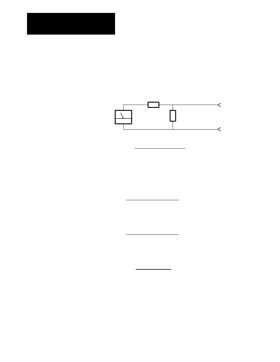
Figure 4.8 uses a l0k ohm resistor across the input channel. Rl represents
the dropping resistor for the scaling network. To determine the value of Rl
use the equation that follows.
Figure 4.8
Scaling Circuit
R1
10k Ohm
Analog In (+)
Analog In (-)
Tach
Resistors 0.5W, 1%
Tach Velocity (+)
TB3Ć33
TB3Ć34
+
-
(Max Volts Output) x 6666
9V
- 6666 = R1
20k Adapter Board Input Impedance
Tach Velocity (-)
3. The analog input channel on the adapter board must now be scaled to
represent an accurate velocity feedback signal. First determine the
analog input signal for base speed. Parameter numbers are given in ( )
where applicable.
Base Motor Speed (606) x 9V
Max Speed
= Base Speed Input
4. The input voltage at base speed is then converted to Raw Adapter Units
according to the following equation.
Base Speed Input x 2048
10
= Raw Adapter Units
5. The Raw Adapter Units are then used to determine the correct scaling
parameter value according to the equation below.
4096
Raw Adapter Units
= Scaling Parameter Value
6. The Scaling Parameter Value should then be entered into the associated
analog input scaling set-up parameter. This procedure will be correct to
within 5%. Verify that the scaling is correct by measuring the actual
motor velocity with a hand tachometer. Fine tune the scaling by
adjusting the appropriate value to minimize any error.
7. Any drift at zero speed can be minimized by adjusting the offset
parameter associated with the channel in use.