Rockwell Automation 440G-LZ Guard Locking Switch User Manual User Manual
Page 36
36
Rockwell Automation Publication 440G-UM001A-EN-P — November 2013
Appendix B
Typical Installations
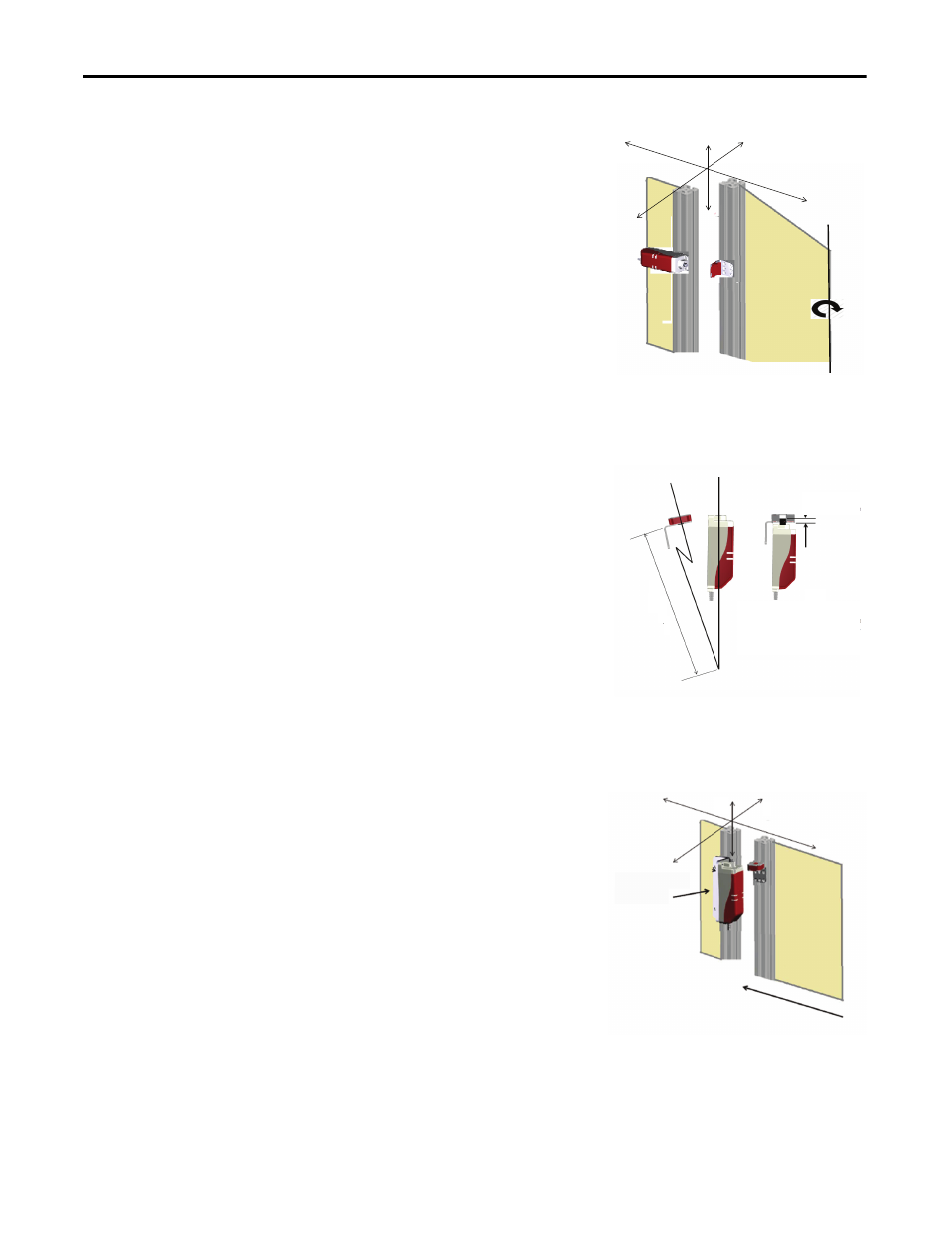
Switch Mounted
Perpendicularly to
Hinge Axis
Switch Mounted to a Sliding
Guard Door
The Z (height) position is adjusted
by sliding the actuator bracket up/
down on the profile. If the setting
gap is centered between the
minimum of 0 mm and the
maximum of 5 mm, a tolerance to
misalignment of ±2.5 mm is
achieved.
The X and Y positions can be
adjusted using spacers
underneath the switch and
appropriate selection of the three
pairs of actuator bracket holes,
once the bracket is centered.
The tolerance to misalignment is
±2.5 mm.
The Z position should be carefully
selected to offset the anticipated
door sag or door drop. At the same
time, ensure that the alignment is
such that it prevents lifting the
door up and off the locking bolt.
Also check to ensure there is no
possibility that the actuator would
collide with the switch when
closing the guard door. It is
essential to check the alignment
periodically throughout the use of
the guard locking switch.
Y
X
Z
2 mm
(at min. radius)
Minimum radius when
guard hinge axis is
perpendicular to the
switch body axis
M
in R 300
mm
The Z (height) position is adjusted
by sliding the actuator bracket up/
down on the profile. If the setting
gap is centered between the
minimum of 0 mm and the
maximum of 5 mm, a tolerance to
misalignment of ±2.5 mm is
achieved.
The X and Y positions can be
adjusted using the slotted holes of
the mounting bracket and
appropriate selection of the three
pairs of actuator bracket holes,
once the bracket is centered.
The tolerance to misalignment is
+/- 2.5 mm.
Mounting
bracket
440G-LZAM2
X
Z
Y