Switch 1 switch 2 switch 3 – Rockwell Automation 440G-LZ Guard Locking Switch User Manual User Manual
Page 27
Rockwell Automation Publication 440G-UM001A-EN-P — November 2013
27
Description of Operation
Chapter 4
Troubleshooting Series
Circuit
Unit Response Times When
Connected in Series
Green
P
ink
Gr
e
y
Red
Yello
w
W
hit
e
Green
Pink
Gr
ey
Red
Yello
w
W
hit
e
Green
Blue
Pink
Gr
ey
Brow
n
Red
Yello
w
W
hit
e
Green
Pink
Gr
ey
Red
Yello
w
W
hit
e
Green
Pink
Gr
ey
Red
Yello
w
W
hit
e
Blue
Blue
Blue
Blue
Brow
n
Brow
n
Brow
n
Brow
n
+24V
+24V
+24V
+24V
0V
0V
0V
0V
0V
0V
RTN
24V DC
Power
Supply
+24
1606-
XL120D
Lock/Unlock
Lock/Unlock
Lock/Unlock
Lock/Unlock
Lock/Unlock
Recoverable
Fault
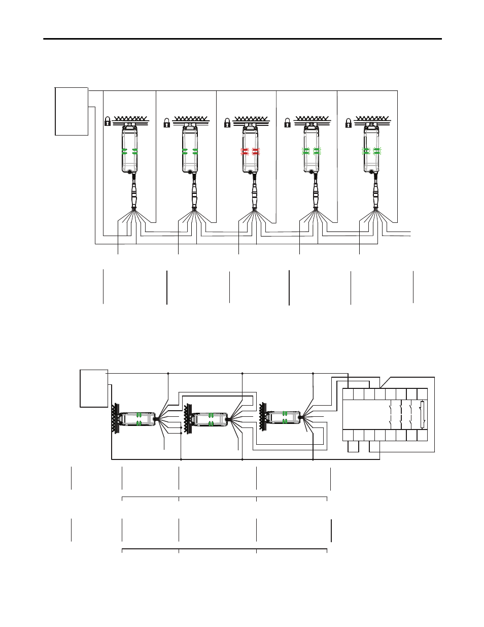
Actuator 1 is in sensing range
and guard is locked.
Guard 1 functions properly.
OSSDs are energized to 24V.
Green LED is ON.
Actuator 2 is in sensing range
and guard is locked.
Guard 2 functions properly.
OSSDs are energized to 24V.
Green LED is ON.
Actuator 3 is in sensing
range and guard is locked.
Guard 3 has a fault.
See Diagnostic table.
Red LED is flashing.
Actuator 4 is in sensing range
and guard is locked. Guard
4 functions properly. Series
inputs are 0V. OSSDs are
de-energized to 0V. Green
LED is flashing to indicate
series inputs are not 24V.
Actuator 5 is in sensing range
and guard is locked. Guard 5
functions properly.
Series inputs are 0V. OSSDs
are de-energized to 0V. Green
LED is flashing to indicate
series inputs are not 24V.
OSSDs
are OFF
Switch 1
Switch 2
Switch 3
Switch 4
Switch 5
A
c
tuat
or 1
A
c
tuat
or 2
A
c
tuat
or 3
S
wit
ch 1
S
wit
ch 2
S
wit
ch 3
RTN
24V DC
Power
Supply
+24
1606-
XL120D
Gr
een
Pink
Grey
Brown
Red
Yel
White
A2
440R-N23132
Initial Conditions:
All switches are
locked
Switch 1 receives
Unlock command
(guard can then
be opened).
L
ock/unlock
co
mm
and
Switch 2 drops the 24 volts
(red and yellow) from
switch 1 OSSD outputs.
Green LED flashes.
Switch 3 drops the 24 volts
(red and yellow ) from
switch 3 OSSD outputs.
Green LED flashes.
Pink
Grey
Red
Yel
White
Gr
een
Blue
Pink
Grey
Red
Yel
White
S11
41
33
23
13
S12
S52
S21 S22
42
34
24
14
A1
S34
200 ms
150 ms
100 ms
0 ms
650 ms
625 ms
600 ms
0 ms
Switch 1 guard is
closed
Switch 1 OSSD
outputs are
energized.
Switch 2 OSSD inputs (red
and yellow) transition to
24V DC from switch 1 OSSD
outputs. Switch 2 OSSD
outputs are energized.
Switch 3 OSSD inputs (red
and yellow) transition to
24V DC from switch 2
OSSD outputs. Switch 3
OSSD outputs are energized.
Gr
een
Br
own
Blue
Br
own
Blue
Switch 1
Switch 2
Switch 3