160 ssc drive parameters, Chapter 5, Profibus parameter descriptions and data protocol – Rockwell Automation 160PD1 160 Profibus Communication Module User Manual
Page 21: 160 ssc drive parameters -1, Chapter
Chapter
5
Profibus Parameter Descriptions
and Data Protocol
This chapter provides a listing and description of the Bulletin 160
Drive parameters related to Network Operation, and the PD1 Module
Data Protocol information.
Important: Refer to your 160 SSC™ Variable Speed Drive (Series C)
User Manual for drive parameter descriptions.
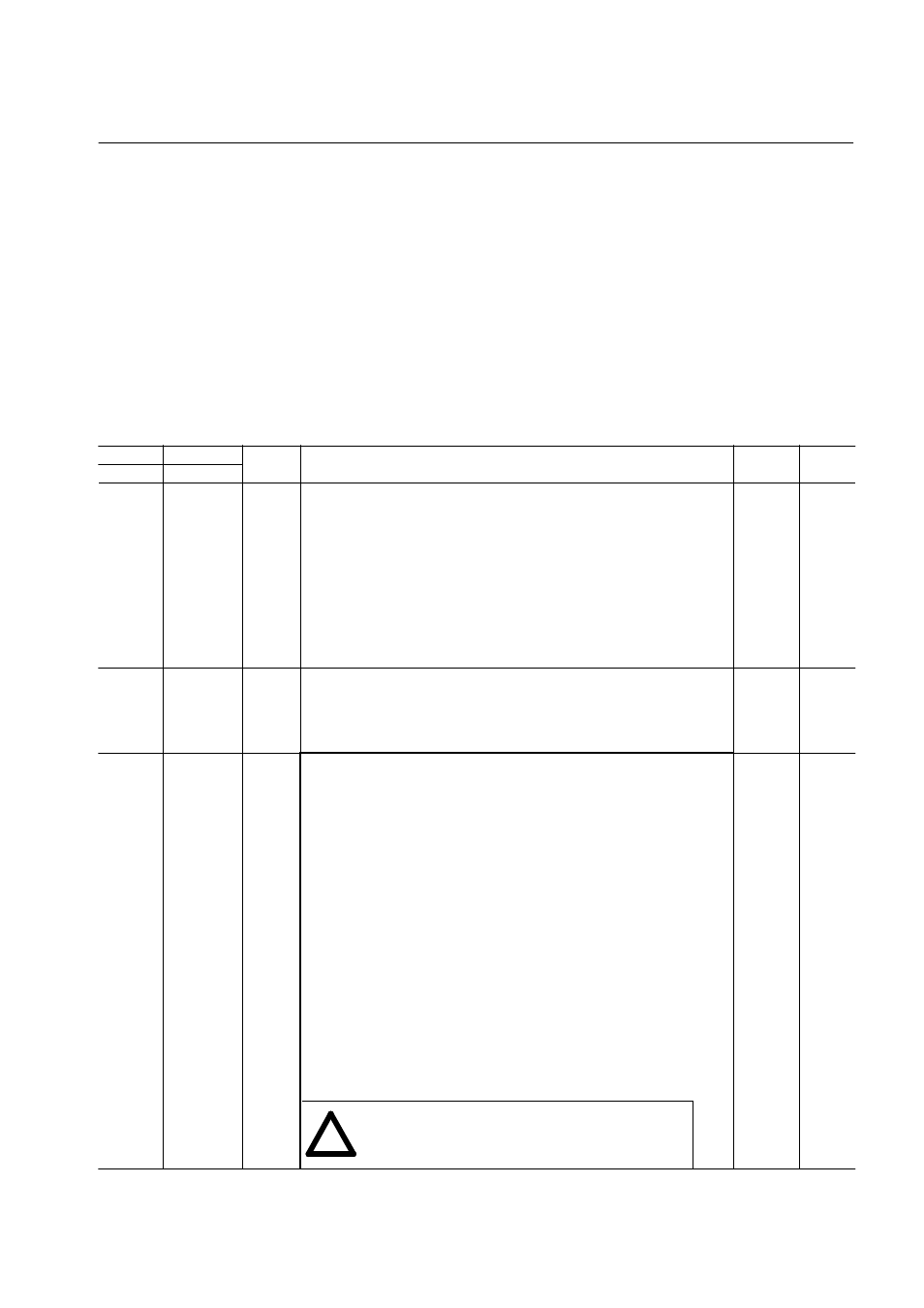
160 SSC Drive Parameters
Drive
PD1 (Tab. 5E)
Access
[Parameter Name] and Description
Min./Max.
Values
Default
Param. No Param. Oper.
46
4
5
Read
write
[Input Mode]
Configures the TB3 control inputs for various 3-wire or 2-wire control schemes.
Also enables/disables the program keypad module input control.
Settings: must be set to either
2 = Program Keypad Module control or
6 = 2-wire TB3 Control/Keypad or Communication control
A contact closure on TB3 terminals 7 and 8 is required for the drive to respond to a
Run command.
Important: This parameter cannot be programmed while the drive is running.
In addition, power must be cycled or P56 - [Reset Function] must be
set to 2 for the change to take effect.
0/9
0
59
4
5
Read
Write
[Frequency Select]
Selects the source of the frequency command for the drive.
The reference to P58 - [Internal Frequency] is bipolar, so a positive reference gives
forward rotation, and a negative reference gives reverse direction.
Settings:must be set to 1 = internal freq. command from P58 - [Internal Frequency].
0/1
0
66
4
5
Read
Write
[RPM Scaling]
A scaling factor is required to interpret a speed reference in RPM at the [Maximum
Frequency] of the drive. The 160 Drive parameter P66 - [Preset Frequency 5] is
used by the PB1 Module for this purpose.
P66 = rRPM / rf
rf:
required motor frequency to achieve rRPM
rRPM:
final RPM at application output (e.g. speed at gear box output),
which will be displayed at Profibus Master
Application Speed [rpm] = Drive Output Frequency x P66 [RPM Scaling]
e.g.
1500 rpm = 50 Hz x 30
(4 pole motor) P66 = 30.0 (300)
900 rpm = 60 Hz x 15
(8 pole motor) P66 = 15.0 (150)
Gear Box 1:20: 75 rpm = 50 Hz x 1.5
(4 pole motor) P66 = 1.5 (15)
For network operation the P66 values in brackets are valid, which are ten times the
values for keypad operation.
If P66 - [RPM Scaling] is set to 0, speed reference may be sent via the network
directly in 1/10 of Hz.
e.g. SpeedRef [Hz] (Profibus) = 405 results in 40.5 Hz of output frequency.
Speed feedback is considered to be P01 - [Output Frequency],
which reflects the output frequency considering ramp rates.
0-240
[0-2400]
50
ATTENTION: Unpredictable motor speed can cause death,
injury or equipment damage. Do not use P66 as the [Preset
Frequency 5] function via control terminal wiring.
!